The ...Distributed Control System (DCS) CONTENTS
The ...Distributed Control System (DCS) CONTENTS
The ...Distributed Control System (DCS) CONTENTS

You also want an ePaper? Increase the reach of your titles
YUMPU automatically turns print PDFs into web optimized ePapers that Google loves.
<strong>Distributed</strong> <strong>Control</strong> <strong>System</strong> (DCS)<strong>CONTENTS</strong>:1) Introduction2) Architecture3) CPU4) Analog Input Module5) Digital Input Module6) Analog Output Module7) Digital Output Module8) Communication <strong>System</strong>9) Human Interface system (HIS)10) Applications
Introduction:A distributed control system (DCS) refers to a control system usually ofa manufacturing system, process or any kind of dynamic system, in whichthe controller elements are not central in location (like the brain) but are distributedthroughout the system with each component sub-system controlled by one or morecontrollers. <strong>The</strong> entire system of controllers is connected by networks forcommunication and monitoring. DCS is a very broad term used in a variety ofindustries, to monitor and control distributed equipment.A DCS typically uses custom designed processors as controllers and usesboth proprietary interconnections and communications protocol forcommunication. Input and output modules form component parts of the DCS. <strong>The</strong>processor receives information from input modules and sends information tooutput modules. <strong>The</strong> input modules receive information from input instruments inthe process (or field) and transmit instructions to the output instruments in thefield. Computer buses or electrical buses connect the processor and modulesthrough multiplexer or demultiplexers. Buses also connect the distributedcontrollers with the central controller and finally to the Human–machineinterface (HMI) or control consoles.CENTUM is the generic name of Yokogawa’s distributed control systems(referred to as “DCS” ) for small- and medium-scale plants (CENTUM CS 1000),and for large scale plants (CENTUM CS 3000).
Architecture:<strong>The</strong> hardware architecture of CENTUM CS 1000 has been shown below ingiven figure. <strong>The</strong> description of CENTUM CS 1000 has been given aftersubdividing it in some smaller areas as CPU, Battery Units, Power supply units,I/O Modules, communication cards, Human interface system (HIS).
CPU:CPU CARD:<strong>The</strong>re are two models of CPU card: <strong>The</strong> CP701 for basic systems and CP703 for enhanced systems. <strong>The</strong> basic system model has 8 MB of memory, whilethe enhanced system model has 16 MB. <strong>The</strong> model chosen depends on the type ofsystem software used. <strong>The</strong> main memory is ensured of high reliability by errorcorrection code (ECC).
<strong>The</strong> redundancy architecture of the CPU is referred to as a synchronous hotstandby system, which is the fundamentally the same as that of the CENTUM CS,the only difference being the addition of the new error detection and protectionfunctions. <strong>The</strong>se functions set write protected areas in each CPU card to protect theprogram and database areas against illegal address writing instruction from theother CPU card, and thereby prevents both card from failing due to illegal accessescaused by malfunctions in MPU. Other newly added functions include the memorymanagement unit (MMU) and write protection which ensure data integrity, theparity check of addresses and data, the ECC memory, and a two wire signal selfchecker.Power Supply Card:<strong>The</strong> power supply card is designed to supply power to the common nests,such as the CPU cards, and up to five I/O module nests. Standardizing the outputvoltages to +5 V DC has simplified the circuit and structure and reduced thenumber of parts. This allowed a power-factor Improvement unit to be built in so asto comply with the aforementioned EN61000-3-2, class A standard (relating topower line harmonics). <strong>The</strong> +5V DC outputs from the two power supply cards passthrough diodes so that they can be coupled externally for redundancy purposes.<strong>The</strong> input-voltage monitoring signal (AC ready) and output-voltagemonitoring signal (DC ready) together with the guaranteed retention time of the+5V DC output, enable to control to continue over a temporary power failure. <strong>The</strong>output voltage retention time immediately after a power failure is clearly defined inthe specifications since it is closely related to the software saving process in theCPU card.
Nest Configuration:<strong>The</strong> FCS nest is composed of VL Net couplers, battery units for backing upthe CPUs’ main memory, a backboard, a power distribution board, and a readysignal output unit in addition to the CPU cards and power supply card. A FCSmodel has five I/O modules nest.Input & Output Modules:<strong>The</strong> I/O modules convert the analog or digital signals from the fieldequipment then pass to field control stations or vice versa to convert the signalsfrom the field control station to the signals for the field equipment. <strong>The</strong> I/O modulecan be categorized into the following seven main types-• Analog I/O module• Multipoint control analog I/O module• Relay I/O module• Multiplexer module• Digital I/O module• Communication module• Communication card
Analog Input Module:List of I/O Modules Installable in Analog I/O Module Nest:Types Model NameAAM10Analog I/O ModuleAPM11AAM50AAM51Wiring of Analog I/O Module:Current/voltage input module(Simplified type)Current/voltage input moduleAAM11AAM11BCurrent/voltage input module(supports BRAIN)AAM21 mV, thermocouple, RTDinput moduleAAM21J mV, thermocouple, RTDinput modulePulse input moduleCurrent output moduleCurrent/voltage output moduleModels AAM10, AAM11, AAM11B, AAM21, AAM21J, APM11, AAM50,AAM51
If output signal between 1 - 5V DC needs to be output to a recorder, etc.,connect the Model AKB301 cable to the (CN1) connector. For example, to outputsignal from the terminal block TE16 to the recorder, connect cable Model AKB301between CN1 and the terminal block.Digital I/O Module:<strong>The</strong> digital I/O module is configured by the card unit and either the terminalunit or connector unit. It inputs and outputs 16 or 32 signal points and convertssignals. Since the types or I/O signals are software-set, no control switch or knob isfound on this module.<strong>The</strong> table below shows the types of digital I/O modules.TypesTerminal typeConnectortypeModelsADM11TADM12TADM51TADM52TADM11CADM12CADM51CADM52CTerminalUnit/Connector Unit/Card Unit Names (*1)ADT16 (terminal)ADM11 (card)ADT32 (terminal)ADM12 (card)ADT16 (terminal)ADM51 (card)ADT32 (terminal)ADM52 (card)ADC16(connector)ADM11 (card)ADC32 (connectorADM12 (card)ADC16 (connectorADM51 (card)ADC32(connector)ADM52 (card)Digital I/O ModuleNamesContact input module(16-point, terminaltype)Contact input module(32-point, terminaltype)Contact outputmodule (16-point,terminal type)Contact outputmodule (32-point,terminal type)Contact input module(16-point, connectortype)Contact input module(32-point, connectortype)Contact outputmodule (16-point,connector type)Contact outputmodule (32-point,connector type)
Wiring of Digital I/O Module (Connector Type):Digital I/O module (connector type)Models ADM11C, ADM12C, ADM51C, ADM52C
Communication Cards:<strong>The</strong> communication cards are used to realize the general-purposecommunication of field control station and subsystems via serial links, so that thesubsystem may be controlled or monitored.Different from the above mentioned cards, the communication package withsubsystems is prepared for ACM21 and ACM22 so that the general-purposecommunication may be conveniently realized. <strong>The</strong> ACM71 Ethernetcommunication module receives/sends data from/to subsystems such as MELSECvia Ethernet.Communication card models:ACM21: RS-232C communication cardACM22: RS-422/RS-485 communication cardACM71: Ethernet communication module
HIS Operation And Monitoring Windows:<strong>The</strong>re are different operational and monitoring windows, which have to defineduring designing Human Interface Station (HIS).<strong>The</strong> different windows are shownbelow:1) Basic Windows for Operation and Monitoring1. <strong>System</strong> Message Window2. Navigator Window2) Windows Convenient for Operation and Monitoring1. Graphic Window2. Trend Window3. Tuning Window4. Faceplate Window5. Operator Guide Window6. Process Alarm Window7. Message Monitor Window8. SFC Window9. Logic Chart Window10. Sequence Table Window11. <strong>Control</strong> Drawing Window12. Help Dialog Box3) Windows for Batch Operation and Monitoring4) Windows for Process Status and Operation Record Configuration1. Process Report Window2. Historical Message Report Window5) Windows for <strong>System</strong> Administration
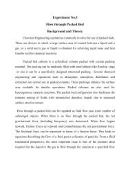
How the HIS looks like:<strong>The</strong> human interface system programmed for a project/plan is designed insuch a way that it would be easy for the operator to understand all the operationsoccurred in the plant. <strong>The</strong> example of visualization of a reactor control power planthas been given below:
Example2:Substation Automation: Visualization of typical substation comprising twoincomers and four feeders.
How the faceplate looks like:Faceplate window is a type of window, where the process variation, switchstatus has been displayed.
Applications:A typical DCS consists of functionally and/or geographically distributeddigital controllers capable of executing from 1 to 256 or more regulatory controlloops in one control box. <strong>The</strong> input/output devices (I/O) can be integral with thecontroller or located remotely via a field network. Today’s controllers haveextensive computational capabilities and, in addition to proportional, integral, andderivative (PID) control, can generally perform logic and sequential control.Modern DCSs also support neural networks and fuzzy application.DCSs may employ one or more workstations and can be configured at theworkstation or by an off-line personal computer. Local communication is handledby a control network with transmission over twisted pair, coaxial, or fiber opticcable. A server and/or applications processor may be included in the system forextra computational, data collection, and reporting capability.<strong>Distributed</strong> control systems (DCSs) are dedicated systems used to controlmanufacturing processes that are continuous or batch-oriented, such as –1) Electrical power grids and electrical generation plants2) Environmental control systems3) Traffic signals4) Radio signals5) Water management systems6) Oil refining plants7) Metallurgical process plants8) Chemical plants9) Pharmaceutical manufacturing10) Sensor networks11) Dry cargo and bulk oil carrier ships etc.
Conclusion:<strong>The</strong> development of CENTUM CS 1000 was accomplished in a short periodof time by using the parts and technologies field proven in CENTUM CS systemwherever possible. It is a low end model in the CENTUM CS series and is actingas a key product for the global market taking over from the microXL system. <strong>The</strong>CENTUM series hardware has identical architecture for plants of all scales. <strong>The</strong>CENTUM CS 1000 has been assessed and updated so as to meet the everincreasing market needs.