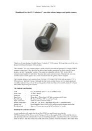
Handbook for the Starlight Xpress SXV AO unit
Handbook for the Starlight Xpress SXV AO unit
Handbook for the Starlight Xpress SXV AO unit

You also want an ePaper? Increase the reach of your titles
YUMPU automatically turns print PDFs into web optimized ePapers that Google loves.
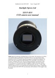
<strong>Handbook</strong> <strong>for</strong> <strong>the</strong> <strong>Starlight</strong> <strong>Xpress</strong> <strong>AO</strong> <strong>unit</strong>Issue 1 21/8/2005The most common method of shifting an image <strong>for</strong> <strong>AO</strong> purposes is to use a ‘tip-tilt’mirror to reflect <strong>the</strong> beam through a variable angle. This works well, but deviates <strong>the</strong>optical path through 90 degrees and takes up a considerable back focal distance. Itsmotion sensitivity is also affected by <strong>the</strong> distance between <strong>the</strong> mirror and <strong>the</strong> CCD. A‘straight though’ device is more convenient and optically shorter, so <strong>the</strong> SX <strong>unit</strong> wasdesigned with this in mind. A secondary advantage of <strong>the</strong> straight through design is that itis possible to construct a system that has a well defined optical deviation <strong>for</strong> a definedinput signal. This means that <strong>the</strong> ‘sensitivity’ of <strong>the</strong> system in pixels shift per input step isessentially constant and is independent of <strong>the</strong> optical system used and <strong>the</strong> distancebetween <strong>the</strong> CCD and <strong>AO</strong>.The <strong>AO</strong> element is a Multi-coated AR bloomed plane-parallel optical window with athickness of 12mm and a diameter of 40mm. This element can be tilted by up toapproximately +/- 3 degrees, by rotating four small stepper motors at <strong>the</strong> periphery of <strong>the</strong>aluminium carrier plate. Converging light from <strong>the</strong> telescope objective lens or mirror,passes through <strong>the</strong> window on its way to <strong>the</strong> CCD chip, but is essentially unaffectedwhen <strong>the</strong> window is perpendicular to <strong>the</strong> beam. However, when <strong>the</strong> window is tilted, <strong>the</strong>converging beam is displaced by an amount which can be defined as approximately0.075mm per 1 degree of tilt. The maximum image deviation is <strong>the</strong>re<strong>for</strong>e approximately+/- 0.15mm in both <strong>the</strong> X and Y planes. This corresponds to about +/- 23 pixels on <strong>the</strong>CCD of an <strong>SXV</strong>-H9 camera.The <strong>AO</strong> <strong>unit</strong> is usually controlled by serial data from an RS232 port. This port can be oneof those provided on most PCs, or <strong>the</strong> serial interface of an <strong>SXV</strong> camera (if supported by<strong>the</strong> software package in use). A USB to serial adaptor can also be used on a PC withoutnative serial ports. The serial data input of <strong>the</strong> <strong>AO</strong> is an RJ11 socket and so a lead with anRJ11 to 9 pin ‘D’ style socket is provided to enable connection to a standard serial port.The computer port should be set to 9600B, 8 bits data, 1 stop bit, no parity.A typical application of <strong>the</strong> <strong>AO</strong> <strong>unit</strong> <strong>for</strong> off-axis guiding:The following diagram shows how <strong>the</strong> <strong>AO</strong> <strong>unit</strong> may be used with <strong>the</strong> optional off-axisguider (OAG) and an SX CCD camera. This is likely to be <strong>the</strong> normal configuration <strong>for</strong>most imagers, as it offers accurate guiding which is free of flexure and mirror shiftproblems. The OAG consists of a short aluminium barrel with a pick-off prism whichfeeds light to an <strong>SXV</strong> guide camera, mounted at <strong>the</strong> end of a short extension tube. Theguide camera position is designed to be close to <strong>the</strong> correct focal distance when a<strong>Starlight</strong> <strong>Xpress</strong> camera is mounted on <strong>the</strong> main optical output of <strong>the</strong> OAG and broughtinto focus. Any small errors may be corrected by loosening <strong>the</strong> two set screws in <strong>the</strong>threaded collar and sliding <strong>the</strong> camera into <strong>the</strong> correct position.The OAG is attached to <strong>the</strong> <strong>AO</strong> <strong>unit</strong> by two set screws which engage with a grooved ringat <strong>the</strong> output of <strong>the</strong> <strong>AO</strong> assembly. Please note that <strong>the</strong> guider barrel should be oriented sothat it projects along <strong>the</strong> line which joins <strong>the</strong> North and South motors. When locatedproperly, <strong>the</strong> two RJ11 sockets on <strong>the</strong> <strong>AO</strong> will be at <strong>the</strong> bottom of <strong>the</strong> <strong>unit</strong>, diametricallyopposite to <strong>the</strong> guider barrel. The long axis of <strong>the</strong> CCD in <strong>the</strong> guide camera should be