FLUID COUPLINGS
FLUID COUPLINGS
FLUID COUPLINGS
- No tags were found...

Create successful ePaper yourself
Turn your PDF publications into a flip-book with our unique Google optimized e-Paper software.
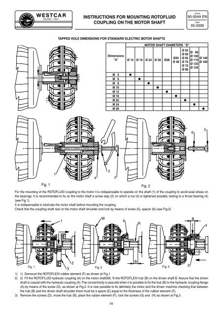
W E S T C A RMILANOITALYMILANO - ITALYINSTRUCTIONS FOR MOUNTING ROTO<strong>FLUID</strong>COUPLING ON THE MOTOR SHAFTSheet90-004A ENDate05-2006TAPPED HOLE DIMENSIONS FOR STANDARD ELECTRIC MOTOR SHAFTSMOTOR SHAFT DIAMETERS “D”ADimensions“A”Ø 14 Ø 19 Ø 24 Ø 28 Ø38Ø42Ø 48Ø 55Ø 60Ø 65Ø 70Ø 75Ø 80Ø 90Ø 100Ø 140Ø 110Ø 160Ø 125Ø 135D1M 5M 6M 8M 10M 12M 16M 20M 24M 36●●●●●●●●●651432Fig. 1 Fig. 2For the mounting of the ROTO<strong>FLUID</strong> coupling to the motor it is indispensable to operate on the shaft (1) of the coupling to avoid axial stress onthe bearings. It is recommended to fix on the motor shaft a screw stay (2) on which a nut (3) is tightened possibly resting to a thrust bearing (4)(see Fig.1).It is indispensable to lubricate the motor shaft before mounting the coupling.Check that the coupling shaft rest on the motor shaft shoulder and lock by means of screw (5), spacer (6) (see Fig.2)1M4RB4Fig. 132Fig. 21) 1) Demount the ROTOFLEXI rubber element (F) as shown at Fig.12) 2) Fit the ROTO<strong>FLUID</strong> hydraulic coupling (A) on the motor shaft(M), fit the ROTOFLEXI hub (B) on the driven shaft ©. Assure that the drivenshaft is coaxial with the hydraulic coupling (A). The concentricity is assured when it is possible to fix the hub (B) to the hydraulic coupling flange(A) by means of the screw (D), as shown at Fig.2. It is now possible to fix definitely the motor and the driven machine checking that betweenthe hub (B) and the driven shaft shoulder there must be a space (E) equal to the thickness of the rubber element (F).3) Remove the screws (D), move the hub (B), place the rubber element (F), lock the screws (G) and (H) as shown at Fig.3.50BFig. 35