McConnel Magnum 130 Flail Mower Operators and Parts Manual
McConnel Magnum 130 Flail Mower Operators and Parts Manual
McConnel Magnum 130 Flail Mower Operators and Parts Manual

You also want an ePaper? Increase the reach of your titles
YUMPU automatically turns print PDFs into web optimized ePapers that Google loves.
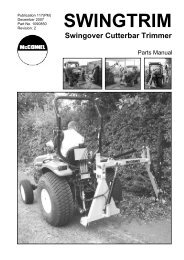
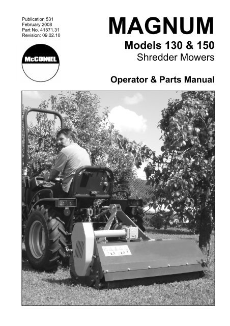
Publication 531February 2008Part No. 41571.31Revision: 09.02.10MAGNUMModels <strong>130</strong> & 150Shredder <strong>Mower</strong>sOperator & <strong>Parts</strong> <strong>Manual</strong>
IMPORTANTVERIFICATION OF WARRANTY REGISTRATIONDEALER WARRANTY INFORMATION & REGISTRATION VERIFICATIONIt is imperative that the selling dealer registers this machine with <strong>McConnel</strong> Limited beforedelivery to the end user – failure to do so may affect the validity of the machine warranty.To register machines go to the <strong>McConnel</strong> Limited web site at www.mcconnel.com, logonto ‘Dealer Inside’ <strong>and</strong> select the ‘Machine Registration button’ which can be found inthe Service Section of the site. Confirm to the customer that the machine has beenregistered in the section below.Should you experience any problems registering a machine in this manner please contactthe <strong>McConnel</strong> Service Department on 01584 875848.Registration VerificationDealer Name: ……………………..…………………………………………………………….Dealer Address: …….………………………………………………………………………….Customer Name: ……………………..…………………………………………………………Date of Warranty Registration: ……/……/...…… Dealer Signature: ………………..……NOTE TO CUSTOMER / OWNERPlease ensure that the above section above has been completed <strong>and</strong> signed by the sellingdealer to verify that your machine has been registered with <strong>McConnel</strong> Limited.IMPORTANT: During the initial ‘bedding in’ period of a new machine it is the customer’s responsibilityto regularly inspect all nuts, bolts <strong>and</strong> hose connections for tightness <strong>and</strong> re-tighten if required. Newhydraulic connections occasionally weep small amounts of oil as the seals <strong>and</strong> joints settle in – wherethis occurs it can be cured by re-tightening the connection – refer to torque settings chart below. Thetasks stated above should be performed on an hourly basis during the first day of work <strong>and</strong> at leastdaily thereafter as part of the machines general maintenance procedure.TORQUE SETTINGS FOR HYDRAULIC FITTINGSHYDRAULIC HOSE ENDSPORT ADAPTORS WITH BONDED SEALSBSP Setting Metric BSP Setting Metric1/4” 18 Nm 19 mm 1/4” 34 Nm 19 mm3/8” 31 Nm 22 mm 3/8” 47 Nm 22 mm1/2” 49 Nm 27 mm 1/2” 102 Nm 27 mm5/8” 60 Nm 30 mm 5/8” 122 Nm 30 mm3/4” 80 Nm 32 mm 3/4” 149 Nm 32 mm1” 125 Nm 41 mm 1” 203 Nm 41 mm1.1/4” 190 Nm 50 mm 1.1/4” 305 Nm 50 mm1.1/2” 250 Nm 55 mm 1.1/2” 305 Nm 55 mm2” 420 Nm 70 mm 2” 400 Nm 70 mm
WARRANTY POLICYWARRANTY REGISTRATIONAll machines must be registered, by the selling dealer with <strong>McConnel</strong> Ltd, before delivery to the end user.On receipt of the goods it is the buyer’s responsibility to check that the Verification of Warranty Registrationin the Operator’s <strong>Manual</strong> has been completed by the selling dealer.1. LIMITED WARRANTIES1.01. All machines supplied by <strong>McConnel</strong> Limited are warranted to be free from defects in material <strong>and</strong>workmanship from the date of sale to the original purchaser for a period of 12 months, unless adifferent period is specified.1.02. All spare parts supplied by <strong>McConnel</strong> Limited are warranted to be free from defects in material <strong>and</strong>workmanship from the date of sale to the original purchaser for a period of 6 months.1.03. The manufacturer will replace or repair for the purchaser any part or parts found, upon examination atits factory, to be defective under normal use <strong>and</strong> service due to defects in material or workmanship.Returned parts must be complete <strong>and</strong> unexamined.1.04. This warranty does not apply to any part of the goods, which has been subjected to improper orabnormal use, negligence, alteration, modification, fitment of non-genuine parts, accident damage, ordamage resulting from contact with overhead power lines, damage caused by foreign objects (e.g.stones, iron, material other than vegetation), failure due to lack of maintenance, use of incorrect oil orlubricants, contamination of the oil, or which has served its normal life. This warranty does not apply toany expendable items such as blades, flails, flap kits, skids, soil engaging parts, shields, guards, wearpads or pneumatic tyres.1.05. Temporary repairs <strong>and</strong> consequential loss - i.e. oil, downtime <strong>and</strong> associated parts are specificallyexcluded from the warranty.1.06. Warranty on hoses is limited to 12 months <strong>and</strong> does not include hoses which have suffered externaldamage. Only complete hoses may be returned under warranty, any which have been cut or repairedwill be rejected.1.07. Machines must be repaired immediately a problem arises. Continued use of the machine after aproblem has occurred can result in further component failures, for which <strong>McConnel</strong> Ltd cannot be heldliable, <strong>and</strong> may have safety implications.1.08. Except as provided herein, no employee, agent, dealer or other person is authorised to give anywarranties of any nature on behalf of <strong>McConnel</strong> Ltd.1.09. For machine warranty periods in excess of 12 months the following additional exclusions shall apply:1) Hoses, external seals, exposed pipes <strong>and</strong> hydraulic tank breathers.2) Filters.3) Rubber mountings.4) External electric wiring.N.B. Warranty cover will be invalid if any non-genuine parts have been fitted or used. Use of nongenuineparts may seriously affect the machine’s performance <strong>and</strong> safety. <strong>McConnel</strong> Ltd. cannot beheld responsible for any failures or safety implications that arise due to the use of non-genuineparts.
2. REMEDIES AND PROCEDURES2.01. The warranty is not effective unless the Selling Dealer registers the machine, via the <strong>McConnel</strong> website <strong>and</strong> confirms the registration to the purchaser by completing the Verification of WarrantyRegistration in the operator’s manual.2.02. Any fault must be reported to an authorised <strong>McConnel</strong> dealer as soon as it occurs. Continued use of amachine, after a fault has occurred, can result in further component failure for which <strong>McConnel</strong> Ltdcannot be held liable.2.03. Repairs should be undertaken within two days of the failure. Claims submitted for repairs undertakenmore than 2 weeks after a failure has occurred, or 2 days after the parts were supplied will be rejected,unless the delay has been authorised by <strong>McConnel</strong> Ltd.2.04. All claims must be submitted, by an authorised <strong>McConnel</strong> Service Dealer, within 30 days of the date ofrepair.2.05. Following examination of the claim <strong>and</strong> parts the manufacture will pay, at their discretion, for any validclaim the cost of any parts <strong>and</strong> an appropriate labour allowance if applicable.2.06. The submission of a claim is not a guarantee of payment.2.07. Any decision reached by <strong>McConnel</strong> Ltd. is final.3. LIMITATION OF LIABILITY3.01. The manufacturer disclaims any express (except as set forth herein) <strong>and</strong> implied warranties withrespect to the goods including, but not limited to, merchantability <strong>and</strong> fitness for a particular purpose.3.02. The manufacturer makes no warranty as to the design, capability, capacity or suitability for use of thegoods.3.03. Except as provided herein, the manufacturer shall have no liability or responsibility to the purchaser orany other person or entity with respect to any liability, loss, or damage caused or alleged to be causeddirectly or indirectly by the goods including, but not limited to, any indirect, special, consequential, orincidental damages resulting from the use or operation of the goods or any breach of this warranty.Notwithst<strong>and</strong>ing the above limitations <strong>and</strong> warranties, the manufacturer’s liability hereunder fordamages incurred by the purchaser or others shall not exceed the price of the goods.3.04. No action arising out of any claimed breach of this warranty or transactions under this warranty may bebrought more than one (1) year after the cause of the action has occurred.4. MISCELLANEOUS4.01. The manufacturer may waive compliance with any of the terms of this limited warranty, but no waiverof any terms shall be deemed to be a waiver of any other term.4.02. If any provision of this limited warranty shall violate any applicable law <strong>and</strong> is held to be unenforceable,then the invalidity of such provision shall not invalidate any other provisions herein.4.03. Applicable law may provide rights <strong>and</strong> benefits to the purchaser in addition to those provided herein.
EC DECLARATION OF CONFORMITYConforming to EEC Machinery Directive 98/37/EC*We,McCONNEL LIMITED,Temeside Works, Ludlow, Shropshire SY8 1JL.Declare under our sole responsibility that:The product (type) ……………………………………………………………………..Tractor Mounted <strong>Flail</strong> <strong>Mower</strong> / Shredder………………………………………………………………………………………….Product Code …………………………………………………………………………..<strong>Magnum</strong> <strong>130</strong>, <strong>Magnum</strong> 150Serial No. & Date ……………………………………. Type …………………………Manufactured by the above company/* ………………………………………………..………………………………………………………………………………………….(* insert business name <strong>and</strong> full address if not stated above)Complies with the required provisions of the Machinery Directive 98/37/EC, *previously Directive 89/392/EEC as amended by Directives 91/368/EEC, 93/44/EEC<strong>and</strong> 93/68/EEC.The machinery directive is supported by;• BS EN ISO 12100:2003 Safety of Machinery. This st<strong>and</strong>ard is made up of twoparts; Part 1 Terminology, methodology, Part 2 Technical Specifications.• BS EN 1050 Safety of machinery - Principles of risk assessment.• And other national st<strong>and</strong>ards associated with its design <strong>and</strong> construction aslisted in the Technical File.The Machinery Directive is fully implemented into UK law by means of the Supplyof Machinery (Safety) Regulations 1992 (SI 1992/3073) as amended by The Supplyof Machinery (Safety) (Amendment) Regulations 1994 (SI 1994/2063).Signed …………………………..……………………………………………………...on behalf of McCONNEL LIMITEDResponsible PersonStatus: Chief Design Engineer Date: February 2010
LIST OF CONTENTSOPERATOR SECTIONGeneral Information 1Machine Description & Purpose of Use 2Machine Identification 2Technical Data 3Technical Specifications 3Safety Features 4Safety Information 5Safety Decals 6Vehicle/Tractor Preparation 7Machine Attachment 8PTO Shaft 9Setting Up <strong>and</strong> Adjustment 10<strong>Flail</strong>s 10Drive Belts 11Pre-Operational Checks 12Operation 13Detachment <strong>and</strong> Storage 14Maintenance 15Troubleshooting 17PARTS SECTION<strong>Mower</strong> Assembly 19
GENERAL INFORMATIONAlways read this manual before fitting or operating the machine – whenever any doubtexists contact your dealer or the <strong>McConnel</strong> Service Department for advice <strong>and</strong> assistance.Use only <strong>McConnel</strong> Genuine Service <strong>Parts</strong> on <strong>McConnel</strong> Equipment <strong>and</strong> MachinesDEFINITIONS – The following definitions apply throughout this manual:WARNINGAn operating procedure, technique etc., which –can result in personal injury or loss of life if not observed carefully.CAUTIONAn operating procedure, technique etc., which –can result in damage to either machine or equipment if not observed carefully.NOTEAn operating procedure, technique etc., which –is considered essential to emphasis.LEFT AND RIGHT HANDThis term is applicable to the machine when attached to the tractor <strong>and</strong> is viewedfrom the rear – this also applies to tractor references.MACHINE & DEALER INFORMATIONRecord the Serial Number of your machine on this page <strong>and</strong> always quote this number whenordering parts. Whenever information concerning the machine is requested remember also to statethe make <strong>and</strong> model of tractor to which the machine is fitted.Machine Serial Number:Machine Model details:Dealer Name:Dealer Address:Dealer Telephone No:Dealer Email Address:Installation Date:1
MACHINE DESCRIPTION & PURPOSE OF USEThe <strong>Magnum</strong> <strong>130</strong> & 150 series of machines are ‘3-point linkage’ tractor mounted flailmower/shredders designed primarily for the mulching of grasses, brambles, small bushes,branches, vines, <strong>and</strong> general crop residues. Their tough construction <strong>and</strong> working widthsof 1.3 <strong>and</strong> 1.5m make them ideal for general maintenance use on compact tractors ingreen areas, vineyards, orchards, verges, <strong>and</strong> all areas where operating space is at apremium.These machines should only be used to perform tasks for which they were designed – useof the machine for any other function may be both dangerous to persons <strong>and</strong> damaging tocomponents <strong>and</strong> is therefore not advisable.MACHINE IDENTIFICATIONEach machine is fitted with an identification plate with the following information:1. Machine (Part Number)2. Machine Serial No.3. Machine WeightWhen ordering spares or replacement parts fromyour local dealer it is important to quote both PartNumber <strong>and</strong> Serial Number as stated on theidentification plate so the machine <strong>and</strong> model canbe quickly <strong>and</strong> correctly identified.2Machine Identification Plate
SAFETY FEATURESLOCATION OF MACHINE SAFETY FEATURES1. PTO Shaft Shield2. Drive Belt Guard3. Safety Decals4. Protection Flaps5. Side Skids4
SAFETY INFORMATIONGeneral safety rules:▲ Always read <strong>and</strong> follow the instructions for the use <strong>and</strong> maintenance of the machinebefore carrying out any work operations or servicing tasks.▲ Improper use of the machine is both highly dangerous to persons <strong>and</strong> damaging to themachine components – only use the machine for its designated task.▲ Both operators <strong>and</strong> the maintenance fitters should be familiar with the machine <strong>and</strong>fully aware of dangers surrounding improper use or incorrect repairs.▲ Before starting, checks to both tractor <strong>and</strong> machine must be carried out as regards:functionality, road safety, accident prevention rules.▲ Even when using the machine correctly, stones or other objects may be thrown a longdistance. Therefore nobody must st<strong>and</strong> within the danger area. Special attention mustbe paid when working near roads or buildings.▲ Use tractor’s fitted with safety cabs.▲ The condition of flails <strong>and</strong> of machine guards must be checked before beginning thedaily work - they must be replaced if damaged or missing before you use the machine.▲ During checks or repairs, make sure nobody could start the machine by mistake.▲ Never wear loose or fluttering clothes.▲ Never carry passengers on the tractor.▲ Never carry passengers on the machine.▲ Never connect the power takeoff with the engine running.▲ Never approach the machine until the rotor has completely stopped.▲ Do not enter the working zone of the PTO shaft. It is dangerous to approach therotating parts of a machine.▲ Keep the PTO shaft guard in good condition.▲ Before starting, check the surrounding area for the likely presence of children <strong>and</strong>/oranimals.▲ Do not st<strong>and</strong> near the machine when it is operating.▲ The PTO shaft must be assembled <strong>and</strong> disassembled only with the engine stopped<strong>and</strong> the starting key removed.▲ Before connecting the power takeoff, check that the speed <strong>and</strong> the rotational directioncorrespond to those of the machine.▲ Immediately replace missing or damaged safety decals.▲ Before leaving the tractor with the machine attached, proceed as follows:1. Disconnect the power takeoff,2. Put the machine steadily on the ground using the tractor’s hydraulic lift.3. Apply the h<strong>and</strong> brake <strong>and</strong>, if the ground is steeply sloping, wedge the tractor.4. Remove the starting key.5
Transportation Safety▲ In transport, reduce speed, especially on bumpy roads, the weight of the machine mayrender driving difficult <strong>and</strong> damage the machine itself.▲ Ensure the levers that operate the hydraulic lift are locked, to avoid the lowering of themachine during transport.▲ When driving on public roads, respect all road rules in force.▲ Never transport the machine with the rotor running, even for short distances.Operating Safety▲ Pay special attention when working with the machine not to touch fixed objects such asroad drain, walls, shafts, kerbs, guard rails, tracks etc. This could cause the breakageof the flails, which would be thrown out of the machine at very high speed.▲ If wires, ropes or chains should become entangled in the rotor stop immediately toprevent damage or dangerous situations; stop the rotor <strong>and</strong> the tractor, take out thestarting key. Put working gloves on; clear the rotor with the aid of pliers or shears. Donot try to disentangle by inverting the rotational direction of the rotor.▲ Do not use the machine when excessive vibration is experienced, as this may causebreakage <strong>and</strong> serious damage - find the cause of the vibration <strong>and</strong> eliminate it beforeusing the machine again.Although the information given here covers a wide range of safety subjects, it is impossible topredict every eventuality that can occur under differing circumstances whilst operating this machine.No advice given here can replace ‘good common sense’ <strong>and</strong> ‘total awareness’ at all times, but will goa long way towards the safe use of your <strong>McConnel</strong> machine.SAFETY DECALS1. Always switch machine off, remove starting key <strong>and</strong> read instruction manual beforeperforming service or maintenance work on the machine.2. Keep a safe distance from the machine at all times - risk from projection of objects.3. Risk of h<strong>and</strong> injury – always ensure all guard are fitted <strong>and</strong> in place when machineis operating.4. Risk of feet injury – keep at a safe distance from the machine when it is operating.5. Never st<strong>and</strong> or ride on the machine.6
VEHICLE / TRACTOR PREPARATIONWe recommend vehicles are fitted withcabs using ‘safety glass’ windows <strong>and</strong>protective guarding when used with ourmachines.Fit Operator Guard (part no. 73 13 324)using the hooks provided. Shape the meshto cover all vulnerable areas.Remember the driver must be lookingthrough mesh <strong>and</strong>/or polycarbonateglazing when viewing the machine in all positions - unless the vehicle/ cab manufacturercan demonstrate that the penetration resistance is equivalent to, or higher than, thatprovided by mesh/polycarbonate glazing. If the tractor has a roll bar only, a frame must bemade to carry both mesh <strong>and</strong> polycarbonate glazing. The operator should also usepersonal protective equipment to reduce the risk of serious injury such as; eye protection(mesh visor to EN1731 or safety glasses to EN166), hearing protection to EN352, safetyhelmet to EN297, gloves, filter mask <strong>and</strong> high visibility clothing.Vehicle BallastIt is imperative when attaching ‘third-party’ equipment to a vehicle that the maximumpossible stability of the machine <strong>and</strong> vehicle combination is achieved – this can beaccomplished by the utilisation of ‘ballast’ in order to counter-balance the additionalequipment added.Front weights may be required for rear mounted machines to place 15% of total outfitweight on the front axle for stable transport on the road <strong>and</strong> to reduce ‘crabbing’ due to thedrag of the cutting unit when working on the ground.Where a machine works to the side of the tractor rear weights may be required to maintaina reasonable amount of rear axle load on the opposing wheel.All factors must be addressed in order to match the type <strong>and</strong> nature of the equipmentadded to the circumstances under which it will be used - factors that effect stability are:• Centre of gravity of the tractor/machine combination.• Geometric conditions, e.g. position of the cutting head <strong>and</strong> ballast.• Weight, track width <strong>and</strong> wheelbase of the tractor.• Acceleration, braking, turning <strong>and</strong> the relative position of the cutting unit during theseoperations.• Ground conditions, e.g. slope, grip, load capability of the soil/surface.• Rigidity of implement mounting.Suggestions to increase stability:• Increasing rear wheel track - a vehicle with a wider wheel track is more stable.• Ballasting the wheel; it is preferable to use external weights but liquid can be added toaround 75% of the tyre volume – water with anti-freeze or the heavier Calcium Chloridealternative can be used.• Addition of weights – care should be taken in selecting the location of the weights toensure they are added to a position that offers the greatest advantage.• Front axle locking, check with tractor manufacturer.The advice above is offered as a guide for stability only <strong>and</strong> is not a guide to vehicle strength. It istherefore recommended that you consult your vehicle manufacturer or local dealer to obtain specificadvice on this subject, additionally advice should be sought from a tyre specialist with regard to tyrepressures <strong>and</strong> ratings suitable for the type <strong>and</strong> nature of the machine you intend to fit.7
ATTACHING THE MACHINE TO THE TRACTORAttachment of the machine to the tractor should always be performed on a firm level site.Before attachment always ensure:• The machine is in good condition.• All safety guards are in good working condition <strong>and</strong> correctly fitted.• All flails are correctly fitted <strong>and</strong> undamaged.• Lubrication points are well greased <strong>and</strong> the gearbox oil level is correct.• Drive belts are tensioned correctly.• The tractor PTO rpm <strong>and</strong> direction of rotation correspond to that of the machine.ATTACHMENT OF THE MOWERDrive the tractor ‘squarely’ up to the machine.Position the tractors lower linkage at a height where it is approximately in line with thelower linkage points (A) on the machine – refer to photo below.Drive tractor slowly towards the machine until the lower linkage points correspond.Fit linkage pins <strong>and</strong> secure with springclips.Fit top link to upper linkage point (B).Raise the machine slightly on the tractorshydraulics – adjust top link to bring themachine into the perpendicular position.Fit check chains <strong>and</strong>/or stabilisers totractor lower links to centralise <strong>and</strong>secure the machine in position.Fit PTO Shaft <strong>and</strong> attach torque chains –refer to following page for details of shaftmeasurement.Machine attachment points ►TOP LINKAGEThe machines top linkage point (B) has two working modes; floating <strong>and</strong> fixed – refer tophoto below.Floating position (B1) should always be used whenworking on hilly or uneven terrain to protect the machine<strong>and</strong> linkage from damage.Fixed position (B2) may be used when working on evenlevel terrain such as playing fields <strong>and</strong> other similar areasthat present a lower degree of stress on the linkage.Top linkage working positions ►WARNING:Always use top linkage floating position (B1) when working on hilly, sloping or undulatingterrain.8
PTO SHAFTPTO SHAFT MEASUREMENTMeasure the PTO shaft <strong>and</strong> cut to thedimension shown – the finished length of thePTO shaft should be 75mm (3”) less than themeasured distance ‘A’ - between tractorshaft <strong>and</strong> gearbox stub shaft - to enablefitting.NOTE: For subsequent use with differenttractors measure again, there must be aminimum shaft overlap of 150mm (6”).Fit PTO in position <strong>and</strong> attach the torquechains to a convenient location to preventthe shaft guards from rotating.PTO SHAFT LENGTH ADJUSTMENT1. Shorten outer plastic tube to 40mmless than the shortest envisaged shaftlength.2. Remove the marked tube.3. Remove same length from innerplastic tube <strong>and</strong> metal shaft profiles(inner <strong>and</strong> outer).4. De-burr all edges <strong>and</strong> remove ‘swarf’to ensure smooth operation.Approximate overlap length of PTO shaft with machine lowered to the ground ▲Approximate gap length of PTO protection tube with machine in working position ▲Fit torque chains to shaft guards to prevent rotation ►9
SETTING UP AND ADJUSTMENTThe height of cut is dependent on workingconditions <strong>and</strong> volume of material. The cuttingheight can be regulated with the hydraulicsystem on the tractor <strong>and</strong>/or rear rolleradjustment – see photo opposite.The minimum height of cut should be between1 – 3cm.NOTE: The machine must always run on therear roller not the side skids – side skids are aprotection feature <strong>and</strong> in normal workingconditions remain clear of the ground.Do not allow the rotor flails to contact theground - set roller height to allow a minimumflail to ground clearance of 1 to 3cm.FLAILSAs st<strong>and</strong>ard, the machine is equipped with Hammer type flails, but as an option can befitted with Y-blade flails. The hammer type flails are more suited to harder working with theability to cut materials up to 45mm (1¾”) diameter. Y-blade flails can cut up to 30mm (1¼”)diameter material – these figures are under normal use <strong>and</strong> may differ depending on thetype <strong>and</strong> nature of the material being cut.The design of the mower is such that during work the rotor unit cuts the material <strong>and</strong>projects it upwards into the frame, as the material falls back into the rotor it is cut againseveral times until it is small enough to be discharged from the rear of the machine.Hammer <strong>Flail</strong>s10Y-Blade <strong>Flail</strong>sThe rotor unit should be inspected on a daily basis prior to work to check for damaged ormissing flails – always replace damaged or missing flails immediately. <strong>Flail</strong> bolts should bechecked for tightness on a regular basis <strong>and</strong> re-tightened as required before attempting touse the machine.WARNING: Checking of rotor components should only be carried out with tractors engine switchedoff, starting key removed <strong>and</strong> the PTO shaft disconnected. Always ‘prop up’ the machine usingsuitable supports before attempting to inspect or work on components underneath it.
DRIVE BELTSBELT TENSIONIt is important for both optimal machine performance <strong>and</strong>long lasting belt life that the belts are correctly tensionedat all times. Tension is correct when a force of 10 kgexerted on the belts at their mid-point between the upper<strong>and</strong> lower pulleys deviates the belts by 15mm.After an initial first 2 hours of work check belt tension <strong>and</strong>taper locks (indicated 1 & 2 in the photo opposite) <strong>and</strong> tightenif required.If the belts require tensioning follow the procedurestated below.BELT ADJUSTMENTAdjustment of the belt tension is performed by looseningthe adjuster locking nut <strong>and</strong> turning the adjuster bolt toincrease or decrease the pressure of the tensionerpulley on the belts until belt deviation matches therequired measurement – see photo opposite. Belttensioning should be performed when the belts are cold.A – Adjuster locknutB – Adjuster boltNo other adjustment or maintenance is required on thebelt tensioning system other than routine inspection <strong>and</strong>general cleaning of components when inspecting beltwear.Belt tension <strong>and</strong> adjuster locationWARNING: Checking of belts <strong>and</strong> drive components shouldonly be carried out with tractors engine switched off, startingkey removed <strong>and</strong> the PTO shaft disconnected. Never attempt torun the machine with the belt guard removed.Refit belt guarding before running the machine ►11
PRE-OPERATIONAL CHECKSBefore commencing work with the machine the following checks should be performed:• Make a visual inspection of the machine to ensure it is in good operational condition.• Check all safety guarding is in position <strong>and</strong> in full working order.• Check rotor for missing or damaged flails <strong>and</strong> replace if required.• Check all greasing points are well lubricated.• Check gearbox oil level.• Check belt tension <strong>and</strong> adjust if required.• Check PTO speed <strong>and</strong> direction match that of the machine.12
OPERATIONEnsure that the operator is suitably qualified to use a machine of this nature <strong>and</strong> that theyhave fully read <strong>and</strong> understood this manual - they should be aware of all safety aspectsrelating to the safe use of the machine. It is advisable that all ‘first time’ operators practiceusing the machine in a clear safe area prior to work in order to familiarise themselves withits operation.After the initial first 2 hours of work with a new machine, nuts <strong>and</strong> bolts should be checked fortightness <strong>and</strong> the drive belts inspected <strong>and</strong> re-tensioned if required – refer to belt section for details.Prior to starting work the area should be checked for dangerous objects such as largestones, wood, wire, glass etc. – hazardous objects should be removed from the area priorto operation with the machine. The location of unmovable or natural hazards should benoted, or if necessary ‘marked’, to indicate to the operator that the area should either beavoided or additional caution adopted whilst working around the hazard.STARTING WORKWith the machine switched off, lower it into a position approximately 10cm above theground, start the machine <strong>and</strong> allow it to build up to the correct working speed beforegently lowering the it onto the ground - the machine is now in its work position <strong>and</strong> forwardtravel can begin.FORWARD SPEEDThe forward working speed will depend on the working conditions <strong>and</strong> nature of thematerial being cut. Optimal speed will be in the region of 3-8 km/h (2-5 mph).Optimal forward working speed 3-8 km/hRaise the machine before turning or reversingREVERSING & TURNINGWhen reversing or turning the unit the machine must always be lifted clear of the ground toavoid damage.TRANSPORTThe following must be observed at all times when transporting the machine:• Machine must always be switched off.• Machine must be raised.• Speed must be kept to a minimum especially on bumpy roads or terrain.• Always abide with local laws <strong>and</strong> road regulations.• Be aware of the machines width.13
DETACHMENT & STORAGEDETACHING THE MACHINE• Removal of the machine should be performed on a firm level site. The procedure fordetachment is as follows:• Gently lower the machine fully to the ground.• Switch off the tractor <strong>and</strong> remove its starting key.• Remove the PTO driveshaft.• ‘Chock’ the rear roller to prevent movement of the machine during the detachmentprocedure <strong>and</strong> whilst in storage.• Remove the top link <strong>and</strong> both pins from the lower attachment points.• Carefully <strong>and</strong> slowly drive the tractor clear of the machine.• Clean <strong>and</strong> lubricate the machine in preparation for next use.STORAGEFor extended periods of storage it is advisable that the machine be kept in a clean dryenvironment protected from the elements to avoid risk of corrosion. The machine shouldbe thoroughly cleaned <strong>and</strong> lubricated prior to storage. At this point it is good practice tocheck the machine for worn or damaged components - any parts that require replacingshould be ordered <strong>and</strong> fitted at the earliest opportunity so the machine is fully prepared forthe next seasons work.14
MAINTENANCEAll maintenance, cleaning <strong>and</strong> repair operations must be performed with the machinefirmly lowered to the ground <strong>and</strong> detached from the tractor or with the PTO disconnected,engine switched off <strong>and</strong> starting key removed. For any repairs or maintenance thatrequires access from underneath, the machine should be firmly <strong>and</strong> safely raised <strong>and</strong>propped using suitable purpose designed supports capable of bearing the machines fullweight. Care should be adopted at all times when working with or under a raised machine.MAINTENANCE TASKSThe following preventative maintenance tasks should be performed at the timescalesstated to both maximise efficiency <strong>and</strong> prolong the working life of the machine.After first 2 hours of work - new machine or machine fitted with new belts. Check all nuts <strong>and</strong> bolt for tightness – retighten if required. Check belt tension <strong>and</strong> taper lock tightness – adjust / tighten if required (refer to beltsection for details of adjustment).After every 8 hours of work Check all nuts <strong>and</strong> bolt for tightness – retighten if required. Check belt tension <strong>and</strong> adjust if required – refer to belt section for details of adjustment. Check wear <strong>and</strong> condition of flails – replacing missing, or damaged flails immediately. Check condition of safety guards – repair or replace if not performing their function. Lubricate grease points – see below for locations of the machines grease points. Check gearbox oil level – top up if required. Check rotor – remove foreign objects that may be fouling or lodged in the rotor. Check frame <strong>and</strong> 3-point hitch – ensure all components are in a safe working condition.After every 100 hours Grease PTO driveshaft – separate telescopic drive <strong>and</strong> apply grease to internal shaft.Every 12 months Change gearbox oilGrease PointsLubricate the points indicated below using type LIS 3 grease.A. Rear Roller L/H Bearing C. Rotor Shaft L/H BearingB. Rear Roller R/H Bearing D. Rotor Shaft R/H Bearing15
GEARBOX LUBRICATIONThe photo opposite shows the lubricationaccess point for the gearbox – this accesspoint is used for both filling <strong>and</strong> lubricantlevel checking.Lubricant level should be checked on adaily basis during work <strong>and</strong> topped up onlyif required.Checking the level is by removal of the plug– lubricant should be inline with the bottomof the aperture. ‘Topping up’ the lubricant isperformed via the same aperture to a pointwhere the oil starts to ‘dribble’ out. Replace<strong>and</strong> tighten the plugs before using themachine.Gearbox oil should be replaced annually.Gearbox Capacity & Lubricant TypeLocation of gearbox lubricant access plug0.8 Litre SAE90FLAIL REPLACEMENTThe rotor <strong>and</strong> flails should be inspected for wear or damage on a regular basis – missing,damaged or worn flails should be replaced immediately. When replacing a flail thediametrically opposite flail should also be replaced at the same time in order to maintainrotor balance.DANGER: Machine <strong>and</strong> tractor should be switched off <strong>and</strong> the starting key removed at all times wheninspecting or maintaining the machine – Never work on a machine that is switch on <strong>and</strong> running.Always replace flails in opposing pairsROTOR VIBRATIONIf vibration of the rotor is experienced the machine should be stopped immediately – this isoften a sign that a flail is either missing or severely damaged, if this is the case do not usethe machine until the problem has been rectified. If vibration continues, or occurs for noapparent reason, the rotor must be checked <strong>and</strong>, if necessary, rebalanced before usingthe machine again. Contact your local dealer for further advice or assistance on thissubject.16
TROUBLESHOOTINGPROBLEM POSSIBLE CAUSES REMEDIESIrregular CutWorn, bent or broken flails Replace flailsNoiseNoisy gearboxVibrationRPM too lowMachine not level to the groundClogged material caused byexcessive forward speedLoose boltsDamaged componentsLack of lubricationWorn gearsWorn bearingsBroken, worn or missing flailsRotor out of balanceWorn rotor bearingsIncrease RPMCorrect mounting on tractorReduce forward speedCheck <strong>and</strong> tighten boltsRepair or replaceTop up oil to correct levelReplace worn componentsReplace worn componentsReplace flailsBalance or replace rotorReplace rotor bearingsExcessive backlash in joints Worn pins Replace pinsTight bearingsBelts overheatingBearings dirty or ungreasedViolent lowering down ofmachineBelts slipping on pulleys<strong>Flail</strong>s contacting the groundWorking speed too highClean <strong>and</strong> greaseLower machine gentlyTension beltsRaise cutting heightReduce working speedMachine DisposalDisposal of this machine <strong>and</strong> any of its component parts must be performed in aresponsible <strong>and</strong> inoffensive manner respecting all current laws relating to this subject.Materials forming this machine that must undergo differentiated division <strong>and</strong> disposal are:– Steel– Mineral Oil– Rubber– Plastic17
MAGNUMModels <strong>130</strong> &150<strong>Parts</strong> <strong>Manual</strong>18
MACHINE ASSEMBLY – <strong>Magnum</strong> <strong>130</strong> / <strong>Magnum</strong> 150Module(s): 1061960AP, 1061961APMcCONNEL19
MACHINE ASSEMBLY – <strong>Magnum</strong> <strong>130</strong> / <strong>Magnum</strong> 150Module(s): 1061960AP, 1061961APMcCONNELREF DESCRIPTION PART<strong>130</strong> 1501 FRAME - <strong>130</strong> 1061585 1 -FRAME - 150 1061586 - 12 LINKAGE 1061001 1 13 ROTOR - <strong>130</strong> (c/w HAMMER FLAILS) 1061587 1 -ROTOR - <strong>130</strong> (c/w Y-BLADE FLAILS) 1061588 1 -ROTOR - 150 (c/w HAMMER FLAILS) 1061589 - 1ROTOR - 150 (c/w Y-BLADE FLAILS) 1061590 - 14 REAR ROLLER - <strong>130</strong> 1061003 1 -REAR ROLLER - 150 1061591 - 15 BELT SHIELD 1061038 1 -BELT SHIELD 1061592 - 16 SKID - L/H 1061004 1 1SKID - R/H 1061005 1 17 REAR ROLLER BRACKET 1061006 2 28 PTO SHIELD BRACKET 1061007 1 19 GEARBOX L5A - 530 1061008 1 -GEARBOX L5A - 530 LH 1061593 1 -GEARBOX 530-1000RPM 1061594 1 -GEARBOX 530-1000RPM LH 1061595 1 -GEARBOX L5A - 615 1061596 - 1GEARBOX 615-1000RPM 1061597 - 1GEARBOX 615-1000RPM LH 1061598 - 110 GEARBOX PLATE 1061599 1 111 GEARBOX FLANGE 1061009 1 112 GREASE NIPPLE 1061554 2 213 GREASE NIPPLE (ANGLED) 1061558 1 114 PULLEY 200/55-3 1061602 1 115 PULLEY 90/55-3 1061604 1 116 STRAIN PULLEY 1061605 1 117 STRAINER HOLDER 1061606 1 118 TAPER LOCK 1061017 1 119 TAPER LOCK 1061018 1 120 ROTOR SHAFT FLANGE 1061019 2 221 WASHER 1061607 1 122 PIN 1061245 1 123 PIN 1061022 2 224 PTO SHIELD 1061608 1 125 BELT 1061609 3 326 HAMMER FLAIL (St<strong>and</strong>ard) 1061033 18 20a) Y-BLADE FLAIL (Option) 1061034 36 40b) BLADE SLEEVE (Required for Y-<strong>Flail</strong> fitment) 1061416 18 20c) SPACER (Required for Y-<strong>Flail</strong> fitment) 1061036 72 8027 PIN 1061097 3 328 BEARING & CASING 1061610 2 229 BEARING & CASING 1061611 2 220QUANTITY
MACHINE ASSEMBLY – <strong>Magnum</strong> <strong>130</strong> / <strong>Magnum</strong> 150Module(s): 1061960AP, 1061961APMcCONNEL21
MACHINE ASSEMBLY – <strong>Magnum</strong> <strong>130</strong> / <strong>Magnum</strong> 150Module(s): 1061960AP, 1061961APMcCONNELREF DESCRIPTION PARTQUANTITY<strong>130</strong> 15030 BEARING 1061040 1 131 BOLT 93<strong>130</strong>34 4 432 BOLT 92<strong>130</strong>45 7 733 BOLT 92<strong>130</strong>55 4 434 BOLT 92<strong>130</strong>65 15 1535 BOLT 92<strong>130</strong>75 4 436 BOLT 9213125 1 137 BOLT 93<strong>130</strong>76 6 638 BOLT 1061132 18 2039 NUT 9143004 4 440 WASHER 9100104 4 441 LOCKNUT 9163005 13 1342 LOCKNUT 1061042 18 2043 NUT 9143005 9 944 NUT 9117009 2 245 SLIDE PC INT 1061026 1 146 WASHER 9100105 22 2247 WASHER 9100106 12 1248 WASHER 05.281.14 2 249 SPRING WASHER 9100205 23 2350 SPRING WASHER 1061583 2 251 SLIDE PC INT 1061027 1 152 SPLIT PIN 1061077 1 153 BOLT 1061584 6 654 SPRING WASHER 9100206 6 655 BEARING CAP 1061614 1 156 WASHER 9100108 1 157 HOOK FOR PTO SHAFT 1061551 1 158 FLAP BAR - <strong>130</strong> 1061012 1 -FLAP BAR - 150 1061600 - 159 FLAP 140 1061010 7 1060 FLAP 150 1061011 2 -RUBBER GUARD KIT - MAGNUM <strong>130</strong> (OPTION) 1061612RUBBER GUARD KIT - MAGNUM 150 (OPTION) 106161361 ATTACHMENT BAR - <strong>130</strong> 1061406 1 -ATTACHMENT BAR - 150 1061407 - 162 RUBBER GUARD - <strong>130</strong> 1061615 1 -RUBBER GUARD - 150 1061616 - 163 GUARD BAR - <strong>130</strong> 1061617 1 -GUARD BAR - 150 1061618 - 164 BOLT 92<strong>130</strong>55 6 665 WASHER 9100105 6 666 LOCKNUT 9143005 6 622
DECAL KIT – <strong>Magnum</strong> <strong>130</strong>Module(s): 1061704McCONNELREF. QTY. PART No. DESCRIPTION1061704 DECAL KIT - MAGNUM <strong>130</strong>1 1 41.094.03 SERIAL NUMBER PLATE2 4 7103230 POP RIVET3 1 1290527 DECAL - MCCONNEL (BLACK)4 1 1290558 DECAL - MAGNUM (BLACK)5 1 09.821.29 DECAL - COMBINED EURODECAL6 1 09.821.31 DECAL - COMBINED EURODECAL7 1 09.821.34 DECAL - COMBINED EURODECAL8 1 09.811.01 DECAL - 540 MAX (CW)9 1 09.810.01 DECAL - GREASE 8 HRS10 1 1290633 DECAL - <strong>130</strong> (BLACK)23
DECAL KIT – <strong>Magnum</strong> 150Module(s): 1061705McCONNELREF. QTY. PART No. DESCRIPTION1061705 DECAL KIT - MAGNUM 1501 1 41.094.03 SERIAL NUMBER PLATE2 4 7103230 POP RIVET3 1 1290527 DECAL - MCCONNEL (BLACK)4 1 1290558 DECAL - MAGNUM (BLACK)5 1 09.821.29 DECAL - COMBINED EURODECAL6 1 09.821.31 DECAL - COMBINED EURODECAL7 1 09.821.34 DECAL - COMBINED EURODECAL8 1 09.811.01 DECAL - 540 MAX (CW)9 1 09.810.01 DECAL - GREASE 8 HRS10 1 1290678 DECAL - 150 (BLACK)24
<strong>McConnel</strong> Limited, Temeside Works, Ludlow, Shropshire SY8 1JL. Engl<strong>and</strong>.Telephone: 01584 873131. Facsimile: 2601584 876463. www.mcconnel.com