TensiNews 9 - TensiNet
TensiNews 9 - TensiNet
TensiNews 9 - TensiNet

You also want an ePaper? Increase the reach of your titles
YUMPU automatically turns print PDFs into web optimized ePapers that Google loves.
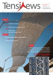
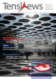
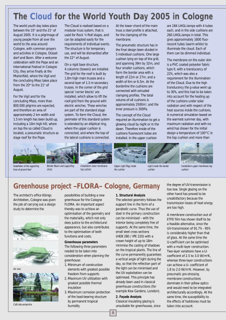
The Cloud for the World Youth Day 2005 in CologneThe world youth day takes placebetween the 15 th and the 21 st ofAugust 2005. It is a pilgrimage ofyoung people from all over theworld to the area aroundCologne, with common prayersand activities in Cologne, Düsseldorfand Bonn. After a welcomecelebration with the Pope and anInternational Festival in CologneCity, they arrive finally at theMarienfeld, where the Vigil andthe concluding Mass takes placefrom the 20 th to the 21 st ofAugust.For the Vigil and for theconcluding Mass, more than800.000 pilgrims are expected,and therefore an area ofapproximately 2 km width and1.5 km length has been build up,including a 10m high hill, whereon top the so called Cloud islocated, a pneumatic structure asstage roof for the Pope.The Cloud is realised based on amodular truss system, that isused for Rock ‘n Roll stages, andcan be adapted easily for therequirements of individual events.The structure is for temporaryuse, and will be dismantled afterthe 22 nd of August.On a rigid base structure,4 columns (towers) are installed.The grid for the roof is built by1.8m high main trusses and asecond layer of 1.3 m secondarytrusses. In the corner of the gridspecial ‘corner blocks’ areinstalled, which allow to lift theroof-grid from the ground withelectric winches. These winchesare part of the standard stagesystem. To form the Cloud, theperimeter of this standard systemis extended by an elliptical ring,where the upper cushion isconnected, and where the top ofthe lateral cushions is connected.At the lower chord of the maintruss a steel profile is attached,for the clamping of themembrane.The pneumatic structure has inthe final design been divided in5 individual cushions. One largecushion lying on top of the grid,and spanning 39m by 32m, andfour smaller cushions, whichform the border area with alength of 22m or 27m, and awidth of 6m or 6.5m. At theborderline the cushions areconnected with extrudedclamping profiles. The totalvolume of all cushions isapproximately 2500m 3 , and theinner pressure is 300Pa.The concept of the Cloudrequired an illumination to get aglowing cloud by night or in thedawn. Therefore inside of thecushions fluorescent tubes areinstalled. In the upper cushionare 184 LHGL-lamps with 4 tubeseach, and in the side cushions are260 LHGL-lamps in total. Thisgives approximately 1800 fluorescenttubes (warm white) toilluminate the cloud. Each ofthem can be dimmed individual.The membrane on the outer skinis a PVC coated polyester fabrictype II, with a translucency of22%, which was also arequirement for the illuminationof the Cloud. Due to the hightranslucency the g-value went upto 30%, and this had to be takeninto account for the heating upof the cushions under solarradiation and with respect of theheat sources inside the cushions.A numerical simulation based onthe warmest summer day, withmaximum radiation and with nowind has shown for the initialdesign a temperature of 100°C inthe top cushion and more thanInstallation of the supportingtruss at ground levelBorder Beam and supportingstrutsInstallation lower membranetop cushionUpper Light Rigg insidethe cushionLight inside the bordercushionInstallation upper membrane topcushionGreenhouse project –FLORA– Cologne, GermanyThe architect's office KönigsArchitekten, Cologne was giventhe job of carrying out a designstudy to determine theAir viewCafé side-perspectivepossibilities of building a newgreenhouse for the CologneFLORA. An important aspectthereby was to achieve anoptimisation of the geometry andthe materiality, which not onlydoes justice to the architecturalappearance, but also contributesto the optimisation of bothfunctions and costs.Greenhouse parametersThe following three parametersneeded to be taken intoconsideration when planning thegreenhouse:1. Minimum of constructionelements with greatest possiblefreedom from supports2. Maximum UV utilization withgreatest possible thermalinsulation3. Maximum corrosion protectionof the load-bearing structureby permanent tropicalhumidity81. Structural AnalysisThe selected geometry follows thesupport line in the form of aparabolic curve. Thus the use ofsteel in the primary constructioncan be minimised – with theinterior being completely free ofsupports. At the same time, thesmall steel cross sections(HEB 280 / IPE 220) with acrown height of up to 18mminimise the casting of shadowson the tropical plants. The line ofthe curve permanently guaranteesa vertical angle of light during theday, so that the reflection part ofthe light can be minimised andthe UV exploitation can beoptimised. This principle hasalready been used in classicalgreenhouse constructions (forexample Kew Gardens, London).2. Façade AnalysisClassical insulating glazing isunsuitable for greenhouses, sincethe degree of UV-transmission istoo low. Single glazing on theother hand has proved to beunsatisfactory because thetransmission losses of heat energyare too high.A membrane construction out ofETFE film has shown itself to bea feasible alternative, since theUV-transmission of 91.7% - 95%is considerably higher than thatof glass. At the same time theU-coefficient can be optimisedwith a multi-layer construction.Two-layer variations have a U-coefficient of 2.5 to 3.0 W/m 2 K,whereas three-layer constructionscan achieve a U- coefficient of1.8 to 2.0 W/m 2 K. However, bypneumatic pre-stressingmembrane constructionsdominate in their pillow opticsand would need to be integratedarchitecturally accordingly. At thesame time, the susceptibility tothe effects of hailstones must betaken into account.