OPERATING and MAINTENANCE MANUAL Jetfans and other Axial ...
OPERATING and MAINTENANCE MANUAL Jetfans and other Axial ...
OPERATING and MAINTENANCE MANUAL Jetfans and other Axial ...

Create successful ePaper yourself
Turn your PDF publications into a flip-book with our unique Google optimized e-Paper software.
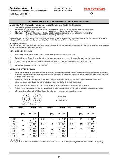
Fan Systems Group Ltd Tel: +44 (14 22 378 131Rochdale Road, Halifax 4HX 8HB, United Kingdom Fax: +44 (14 22) 371 672certified acc. to DIN ISO 900112. DISMANTLING <strong>and</strong> REFITTING of IMPELLERS HAVING TAPERLOCK BUSHESAccessibility: At first the impeller must be made accessible. In the case of radial fans this includes:1. Take off duct system at inlet side of the fan.2. Remove screws at the inlet cone of the casing (includes inlet spigot, protection grill, inlet cone <strong>and</strong>/or inlet duct).3. Carefully take off inlet cone Attention: Do not damage the sealing.4. Attention: Measure the distance between impeller back disc <strong>and</strong> inlet cone <strong>and</strong> maintain it when refitting.Differences in the distance lead to capacity reduction!For axial fans the fan in general must be dismounted <strong>and</strong> placed on a level surface with the impeller pointing upwards. Exceptions are swingout type axial fans where the impeller is accessible after opening the door <strong>and</strong> fans inside jet cowls.Description of function:The hub has a conical inner bore. A conical bush, which is cylindrical inside is inserted. When tightening the fixing screws, the bush betweenshaft <strong>and</strong> hub is exp<strong>and</strong>ed <strong>and</strong> locked in place.DISMOUNTING OF IMPELLERa) If corroded use rust dissolving oil. Do not use hammers, crowbars or <strong>other</strong> use of force.b) Detach all screws. Depending on size of the bush, unscrew one or two screws, oil them <strong>and</strong> screw them into the set bores.c) Tighten screw(s) uniformly, until the bush comes out of the hub, so that the bush can move freely on the shaft.d) Remove impeller with the bush from the shaft.REMOUNTING OF THE IMPELLER1. Clean <strong>and</strong> degrease all uncovered surfaces, such as the bore <strong>and</strong> the conical surface of the taperlock bush as well as the conical boreof the hub. Insert the taperlock bush into the hub <strong>and</strong> superimpose all connection bores (half-thread bores must always have half-plainbores on the opposite side).2. Slightly oil <strong>and</strong> screw in threaded stud (Gr. 1008 - 3030) <strong>and</strong>/or cylindrical screws (Gr. 3535 - 5050). Don’ t fix screws tightly.3. Clean <strong>and</strong> grease shaft. Push disc with taperlock bush onto the shaft until desired place is found.4. When using a slot key, place it first into the slot. Between slot key <strong>and</strong> bore slot there must be a small gap.5. Tighten thread studs <strong>and</strong>/or cylinder screws uniformly by using a screw driver, DIN 911, with the torques indicated in the table.6. After a short time of operation (1/2 or 1 hour) check torque of the screws <strong>and</strong> correct if necessary.◦ fixing bore• pull-off boresmall hublarge hubBush Torque Screws Bush Torque- Screws Bush Torque Screws[Nm] Nb. Size [Nm] Nb. Size [Nm] Nb. Size100811085,6 21/4"BSW2012 31 2 7/16"BSW4040 170 3 5/8"BSW1310131520 23/8"BSW2517 48 2 1/2"BSW4545 192 3 3/4"BSW1210121520 23/8"BSW3020303090 25/8"BSW5050 271 3 7/8"BSW1610161520 23/8"BSW3535 112 3 1/2"BSWFan assemblyCarry out points 1 - 3 in reverse order. Check distances measured under 4. Turn the impeller by h<strong>and</strong> <strong>and</strong> check that it is turning freely.14