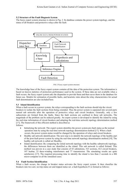
Krisna Kant Gautam et al./ Indian Journal of Computer Science and Eng<strong>in</strong>eer<strong>in</strong>g (IJCSE)5.2 Structure of the Fault Diagnosis SystemThe <strong>fuzzy</strong> expert <strong>system</strong> structure is shown <strong>in</strong> Fig. 2. Its database conta<strong>in</strong>s the <strong>power</strong> <strong>system</strong> topology, and thestatus of all breakers and protective relays after the <strong>fault</strong>.ONLINE DATA FROM POWER STATIONDispatcher<strong>in</strong>ter faceDatabaseFault NetworkIdentificationKnowledge baseHypothesis andcalculationsInference Eng<strong>in</strong>eFault DetectionFIG 2 Fuzzy expert <strong>system</strong> structureThe knowledge base of the <strong>fuzzy</strong> expert <strong>system</strong> conta<strong>in</strong>s all the data of the protection <strong>system</strong>. The <strong>in</strong>formation isbased on known statistics of protection performance used <strong>in</strong> the <strong>system</strong>. If these data are not available when a<strong>fault</strong> occurs, the <strong>fuzzy</strong> expert <strong>system</strong> asks the dispatcher to provide them and then saves them <strong>in</strong> the database forfuture use. Models for estimation of possible <strong>fault</strong>s, and heuristic rules about the relay characteristics for actual<strong>fault</strong> determ<strong>in</strong>ation are also <strong>in</strong>cluded here.5.3 Island IdentificationWhen a <strong>fault</strong> occurs <strong>in</strong> a <strong>power</strong> <strong>system</strong>, the relays correspond<strong>in</strong>g to the <strong>fault</strong> sections should trip the circuitbreakers to isolate the <strong>fault</strong> sections from be<strong>in</strong>g extended. Thus the <strong>power</strong> <strong>system</strong> is separated <strong>in</strong>to several partsnamed sub networks after the operation of protective relays and circuit breakers. Generally, only a fewsubsections are formed from the <strong>fault</strong>s. S<strong>in</strong>ce the <strong>fault</strong> sections are conf<strong>in</strong>ed to these sub networks, Themagnitude of the problem can be reduced greatly. An expert <strong>system</strong> is developed to identify the island by us<strong>in</strong>gthe real-time <strong>in</strong>formation of circuit breakers and adopt<strong>in</strong>g the real-time network topology determ<strong>in</strong>ation method[17]. The framework of this efficient method is described asfollows:Initializ<strong>in</strong>g the network: The expert <strong>system</strong> identifies the <strong>power</strong> <strong>system</strong> pre-<strong>fault</strong> status as the normaloperation state by us<strong>in</strong>g the real-time network topology determ<strong>in</strong>ation method [17]. When a <strong>fault</strong>occurs, the <strong>power</strong> <strong>system</strong> status would be changed by the operation of relays and circuit breakers.Healthy sub network identification: The next step is to identify the network topology of the healthy partof the post-<strong>fault</strong> <strong>power</strong> <strong>system</strong> by us<strong>in</strong>g the real-time network topology determ<strong>in</strong>ation method [18]. Thehealthy sub network is called set Shealthy.Island identification: By compar<strong>in</strong>g the <strong>in</strong>itial network topology with the healthy subnetwork topology,the differences between them are identified as the island. This sub network is called Sisland. Thismethod was proven <strong>in</strong> a case study that consists of 43 substations, 523 sections, 412 circuit breakers,107 busbar, 23 three-w<strong>in</strong>d<strong>in</strong>g transformers and 77 transmission. The simulat<strong>in</strong>g results are quitesatisfactory [17]. The required process<strong>in</strong>g time to identify the island is less than 2 seconds <strong>in</strong> a 486micro-computer <strong>in</strong> all the simulated cases.5.4 Fault Section IdentificationWhen a <strong>fault</strong> occurs, the change <strong>in</strong> breaker status activates the <strong>fuzzy</strong> expert <strong>system</strong>. It then classifies thebreakers <strong>in</strong>to two sets: no-trip status set and tripped status set. a <strong>fault</strong> hypothesis Fi is formed as follows:ISSN : 0976-5166 Vol. 2 No. 4 Aug -Sep 2011 557
Krisna Kant Gautam et al./ Indian Journal of Computer Science and Eng<strong>in</strong>eer<strong>in</strong>g (IJCSE)--------- (1)-----------(2)---------(3)where Ci is one of the possible <strong>fault</strong> sections be<strong>in</strong>g considered; P<strong>fault</strong> is the <strong>fuzzy</strong> set which conta<strong>in</strong> all thepossible <strong>fault</strong> sections and their membership functions; Fi(CB) is the <strong>fuzzy</strong> subset by consider<strong>in</strong>g only thetripped circuit breakers; Fi(RL) is the <strong>fuzzy</strong> subset by consider<strong>in</strong>g only the operated relays.5.5. ConclusionGenerally, a conventional rule-based expert <strong>system</strong> for bulk <strong>power</strong> <strong>system</strong> needs several hundreds of rules. It istime consum<strong>in</strong>g <strong>in</strong> <strong>in</strong>ference procedures to search for suitable rules dur<strong>in</strong>g <strong>in</strong>ferenc<strong>in</strong>g. On the other hand, <strong>fuzzy</strong>set based expert <strong>system</strong>s tend to be much faster compared to traditional rule-based expert <strong>system</strong>s for most ofthe rules are replaced by the calculation of the membership functions of the applicable rules . Only a few rulesor functions are used <strong>in</strong> the <strong>in</strong>ference eng<strong>in</strong>e. The <strong>fuzzy</strong> set approach for uncerta<strong>in</strong>ty process<strong>in</strong>g <strong>in</strong> expert<strong>system</strong>s offers many advantages to compared other approaches to deal with uncerta<strong>in</strong>ty.Small memory space and computer time: The knowledge base is very small because there are only a few rulesneeded dur<strong>in</strong>g <strong>in</strong>ference. The computationtime is therefore also small.o Small number of rules: With properly designed l<strong>in</strong>guistic variables and level of granularity,only a few <strong>fuzzy</strong> rules are needed for each situation.o Flexibility of the <strong>system</strong>: Membership functions represent<strong>in</strong>g the parameters can be changeddynamically accord<strong>in</strong>g to the situation. It is also possible to develop a self-learn<strong>in</strong>g modulethat modifies the grades of membership automatically accord<strong>in</strong>g to chang<strong>in</strong>g situations.5.6 References[1] T. S. Dillon and M. A. Laughton, Expert System Applications <strong>in</strong> Power Systems, Prentice Hall International Series <strong>in</strong> Power SystemsComputation.[2] N. Vadiee and M. Jamshidi, “The Promis<strong>in</strong>g Future of Fuzzy Logic,” IEEE Expert, August 1994, pg. 37.[3] R. Levi, M. Rivers and K. Hickey, “An Intelligent Instrument for High Voltage Equipment Insulation Evaluation,” Proceed<strong>in</strong>gs of the1994 International Conference on Intelligent System Application to Power Systems, France, Sept.[4] 1994, pp. 471-476.[5] S.C. Shapiro, ed., Encyclopedia of Artificial Intelligence, Wiley, New York, 1992.[6] Yuan-Yih Hsu, F. C. Lu, Y. Chien, et al., “An expert <strong>system</strong> for locat<strong>in</strong>g distribution <strong>system</strong> <strong>fault</strong>s,” IEEE Trans. on[7] PWRD, Vol. 5, No. 2, pp366-371.[8] M. Kezunovic, C. W. Fromen, et al., “An expert <strong>system</strong> for transmission substation event analysis,” IEEE Trans. on Power Delivery,Vol.8, No. 4, Oct. 1993, pp1942-1949.[9] J.R. McDonald, G.M.Burt D.J. Young, “Alarm process<strong>in</strong>g and <strong>fault</strong> <strong>diagnosis</strong> us<strong>in</strong>g knowledge based <strong>system</strong>s for[10] transmission and distribution network control,” IEEE Trans. on Power Systems, Vol.7, No.3, Aug. 1992, pp1292-1298.[11] Takafumi Kimura, S<strong>in</strong>ya Nishimatsu, et al., “Development of an expert <strong>system</strong> for estimat<strong>in</strong>g <strong>fault</strong> section <strong>in</strong> control center based onprotective <strong>system</strong> simulation,” IEEE Trans. On Power Delivery, Vol.7, No.1, Jan., 1992, pp167-172.[12] C.A. Protopapas, A.V. Machias, et al., “An expert <strong>system</strong> for substation <strong>fault</strong> <strong>diagnosis</strong> and alarm process<strong>in</strong>g,” IEEE Trans. on PowerDelivery, Vol.6, No.2, April 1991, pp648-655.[13] Benoit Valiquette, Germano Lambert Torres, “An expert <strong>system</strong> based <strong>diagnosis</strong> and advisor tool for teach<strong>in</strong>g <strong>power</strong>[14] <strong>system</strong> operation emergency control strategies,” IEEE Trans. on Power Systems, Vol.6, No.3, Aug. 1991, pp1315-1322.[15] Chihiro Fukui, Junzo Kawakami, “An expert <strong>system</strong> for <strong>fault</strong> section estimation us<strong>in</strong>g <strong>in</strong>formation from protective relays and circuitbreakers,” IEEE Trans. on Power Delivery, Vol. PWRD-1, No.4, Oct. 1986.[16] C.S Chang, J.M. Chen et al., “Power <strong>system</strong> <strong>fault</strong> <strong>diagnosis</strong> us<strong>in</strong>g <strong>fuzzy</strong> sets for uncerta<strong>in</strong>ties process<strong>in</strong>g,” accepted for[17] publication <strong>in</strong> ISAP’96, Orlando, USA.[18] C.S. Chang, J.M. Chen, A. C. Liew, “An expert <strong>system</strong> approach for <strong>fault</strong> <strong>diagnosis</strong> consider<strong>in</strong>g uncerta<strong>in</strong>ties,” Proceed<strong>in</strong>gs ofInternational Conference on Intelligent Manufacture<strong>in</strong>g’95 (ICIM’95), Wuhan, Ch<strong>in</strong>a, June, 1995.[19] Cho H.J., Park J. K., Lee H. J., “A <strong>fuzzy</strong> expert <strong>system</strong> for <strong>fault</strong> <strong>diagnosis</strong> of <strong>power</strong> <strong>system</strong>s,” Proceed<strong>in</strong>gs of ISAP’94, Montpellier,France, Sept., 1994, pp217-222.[20] P. Jarventausta, P. Verho, J. Partanen, “Us<strong>in</strong>g <strong>fuzzy</strong> sets to model the uncerta<strong>in</strong>ty <strong>in</strong> the <strong>fault</strong> location process of[21] distribution networks,” IEEE Trans. on Power Delivery, Vol.9, No. 2, April 1994, pp954-960.[22] Zhu Yongli, Y.H. Yang, B. W. Hogg, W.Q. Zhang, S. Gao, “An expert <strong>system</strong> for <strong>power</strong> <strong>system</strong>s <strong>fault</strong> analysis,” IEEE[23] Trans. on Power Systems, Vol. 9, No. 1, Feb., 1994, pp503- 509.[24] Fushan Wen and Zhenxiang Han, “Optimal <strong>fault</strong> section estimation <strong>in</strong> <strong>power</strong> <strong>system</strong>s us<strong>in</strong>g a genetic algorithm,”[25] accepted for Journal of Electric Power Systems Research.ISSN : 0976-5166 Vol. 2 No. 4 Aug -Sep 2011 558