MIL-C-17 COAXIAL CABLESINTRODUCTIONMIL-C-17 is the government specification document used tostandardize coaxial cables; it has been in use since the 1940’s. Inthe many revisions made to MIL-C-17 over the years, the familiarRG part numbers were superseded by M17 part numbers duringthe 1970s. The benefits of these more recent revisions are discussedunder the following headlines. The most recent andtherefore applicable revision to MIL-DTL-17 is Revision H.Pages 29 through 39 contain a complete listing of all currentM17 cables. For engineering reference, pages 45 through 61 containthe old RG tables. Attenuation and power handling characteristicstables are presented on pages 40 through 44.BENEFITS IN USING MIL-C-17 COAXIAL CABLESRevision E to MIL-C-17 was released in 1976 to better definethe mechanical and electrical requirements for military coaxialcables. For 50-ohm cables, the most important changes were theaddition of swept frequency measurements of both attenuationand structural return loss requirements (VSWR) to 22 differentcables. Before this revision there were no VSWR requirements,and attenuation requirements were only given at two or three discretefrequencies. Other significant changes are described in thefollowing paragraphs.ADHESION REQUIREMENTSMIL-C-17 specifications now contain the minimum and maximumadhesion requirements of the dielectric core to the centerconductor. Prior to revision E, it was possible for a cable to haveso little adhesion that the center conductor in shorter cablescould be pulled out of the entire assembly during the strippingoperation. Or there could be too much adhesion between the coreand the conductor, causing the conductor to break before the dielectriccore could be stripped off. With Revision E, a definite criterionhas been specified.DIMENSIONAL STABILITYRevision E required that all cables be manufactured and testedto a specific maximum shrinkback allowance for the dielectriccore and the jacket. Temperature extremes can cause shrinkbackof the cable jacket which can create a poor termination.ECCENTRICITYBefore Revision E was implemented, eccentricity requirementsapplied only to polyethylene dielectrics. Now eccentricityrequirements have been identified for other kinds of dielectrics(e.g., PTFE). <strong>Cable</strong>s that meet the eccentricity requirement facilitatethe reliable assembly of connector parts and provide lowVSWR ratios.STRESS-CRACK RESISTANCEMIL-C-17 now requires a stress-crack resistance test on allFEP (fluorinated ethylene propylene) and PFA (perfluoroalkoxy)jacketed cables. This test identifies cables with previously undetectedresidual stress that could result in jacket cracking.CONTAMINATIONAlthough earlier MIL-C-17 specifications allowed the use ofsome Type I PVC (polyvinylchloride) for jackets, Revision F hascompletely replaced it with Type II PVC, a non-contaminatingcompound. The plasticizers in Type I PVC can penetrate thebraided shield and migrate into the polyethylene dielectric core,causing a large increase in the dielectric loss portion of attenuation,especially at frequencies above 1 GHz.It should be noted that a cable with a type I PVC jacket can affectother cables in close contact, even if the other cables all haveType IIa jackets.28ATTENUATION AND STRUCTURAL RETURN LOSSMIL-C-17 specifications require that attenuation and structuralreturn loss (VSWR) be completely tested by sweeping 22 different50-ohm cables over the frequency band for which their use isrecommended. Variance in materials or in the manufacturing processcan cause periodic discontinuities along a length of coaxialcable which can introduce resonance peaks (spikes). Thesespikes occur when the discontinuities or changes in electricalcharacteristics are periodic and at half-wave distances.When impedance changes occur periodically, there are frequenciesin which all of the reflections are in phase, resulting in alarge reflected signal or VSWR that is out of proportion to the normalVSWR of the cables and its connectors. Periodic reflectionscan also cause substantial increase in attenuation at the resonancepeaks. In the past, it was very unusual to detect these narrowband, high attenuation spikes when cables were tested for attenuationusing the older MIL-C-17D discrete frequency test procedure(generally at 400 MHz and 3 GHz, and also at 10 GHz forRG-214).Now, however, M17/75-RG214 has continuous swept maximumVSWR and attenuation requirements from 50 MHz to 11GHz. The maximum VSWR is 1.15:1 (23 dB SRL) at 100 MHz increasingto a maximum of 1.33:1 (17 dB structural return loss) at11 GHz. The maximum attenuation is 1.7 dB/100 feet at 50 MHzincreasing to 60 dB/100 feet at 11 GHz.<strong>Coaxial</strong> cables that do not require “full band” swept frequencyperformance can be procured under separate part numbers in anunswept version. The specifications sheets for these unsweptcables recommend that they not be used above 400 MHz. Theuser must decide which cables will best suit the situation basedon cost, application and potential for system growth and improvements.CABLE DESIGNATIONS<strong>Cable</strong>s that are manufactured to MIL-C-17 specifications nolonger carry the RG designation. For example, RG-214 has beenreplaced by M17/75-RG214. In the future, any new cable designwill be designated by an M17 part number only. In addition to theM17 number, all cables are marked with the manufacturer’s nameand government identification number, for example, “M17/75-RG214, MIL-C-17, <strong>Times</strong> <strong>Microwave</strong> Systems, 68999 AA-3409”<strong>Cable</strong>s that are not marked with this information are not qualifiedand there is no guarantee of their performance.MIL-C-17 QPL LISTINGOnly qualified cables should be used for military contracts. Allmanufacturers of MIL-C-17 cables must obtain qualification approvalfor their cables. The qualified products are then listed inQPL-17 which is updated periodically throughout the year.Please note that all RG numbered cables have been cancelledfrom MIL-C-17 and only cables with part numbers starting “MIL/17” should be used for new military contracts. Since there is nolonger any control of “RG” specifications, many cables on themarket with RG designations may be completely different in constructionand performance. The RG tables listed in this catalog,when supplied by <strong>Times</strong>, are manufactured in accordance withthe original specifications sheet released by the military.SPECIAL DESIGNSAlthough MIL-C-17 covers a broad range of cable types, <strong>Times</strong>can also provide technical assistance in designing specializedcables to meet specific system parameters that cannot be metwith existing MIL-C-17 cables. Please contact our Marketing Departmentfor assistance with your specialized need.(800)-TMS-COAX • www.timesmicrowave.com • (203)-949-8400
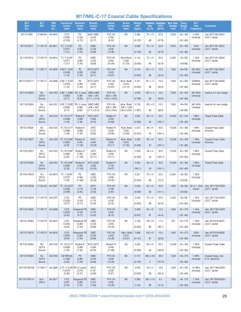
M17/MIL-C-17 <strong>Coaxial</strong> <strong>Cable</strong> SpecificationsM17 M17 TMS Conductor Dielectric Shields Jacket Armor Weight Impedance Capacitance Max Oper. Temp. M17Part QPL Part inches inches inches inches inches lb/ft ohms pF/ft Voltage Range Test CommentsNo. No. (mm) (mm) (mm) (mm) (mm) (kg/m) Vp (%) (pF/m) vrms F (C) FrequencyM17/2-RG6 17-663-83 AA-3810 CCS PE 34SC-34BC PVC-IIA NA 0.082 75 +/-3 20.6 3,000 -40 +185 3 GHz Use M17/180-000010.0285 0.185 0.243 0.332 Unswept LS/LT Jacket(0.724) (4.70) (6.17) (8.43) (0.122) 66 (67.6) (-40 +85)M17/6-RG11 17-100-79 AA-3811 TC 7/.0159” PE 33BC PVC-IIA NA 0.098 75 +/-3 20.8 5,000 -40 +185 1GHz Use M17/181-000010.0477 0.285 0.318 0.405 Unswept LS/LT Jacket(1.21) (7.24) (8.08) (10.29) (0.146) 66 (67.6) (-40 +85)M 17/6-RG12 17-100-79 AA-3812 TC 7/.0159” PE 33BC PVC-IIA Alum.Braid 0.144 75 +/-3 20.6 5,000 -40+185 1 GHz Use M17/181-000020.0477 0.285 0.318 0.405 0.463 Unswept LS/LT Jacket(1.21) (7.24) (8.08) (10.29) (11.76) (0.200) 66 (67.6) (-40+85)M17/15-RG22 17-793-77 AA-3395 2-BC7/ .0152” PE 34TC:34TC PVC-IIA NA 0.134 95 +/- 5 16.0 1.000 -40+185 200 MHz Use M17/182-000010.0456 0.285 0.343 0.420 Unswept LS/LT Jacket(1.16) (7.24) (8.71) (10.67) (0.200) 66 (52.5) (-40 +85)M17/15-RG111 17-793-77 AA-3396 2-BC 7/.0152” PE 34TC:34TC PVC-IIA Alum. Braid 0.161 95 +/- 5 16.0 1,000 -40 +185 200MHz Use M17/182-000020.0456 0.285 0.343 0.420 0.478 Unswept LS/LT Jacket(1.16) (7.24) (8.71) (10.67) (12.14) (0.240) 66 (52.5) (-40 +85)M17/16-RG23 No AA-5160 2-BC 7/.0285” PE: 2 cores 34BC:34BC PVC-IIA NA 0.530 125 +/- 5 12.0 7,000 -40 +185 400 MHz Inactive for new designQPL’d 0.0855 0.380 .438 x .847 .650 x .945 UnsweptSource (2.17) (9.65) (11.1 x 21.5) (16.5 x 24.0) (0.789) 66 (39.4) (-40 +85)M17/16-RG24 No AA-5161 2-BC 7/.0285” PE: 2 cores 34BC:34BC PVC-IIA Alum. Braid 0.730 125 +/-5 12.0 7,000 -40+185 400 MHz Inactive for new designQPL’d 0.0855 0.380 .438 x .847 .650 x .945 .708 x 1.003 UnsweptSource (2.17) (9.65) (11.1 x 21.5) (16.5 x 24.0) (18.0 x 25.5) (1.087) 66 (39.4) (-40 +85)M17/19-RG25 No AA-5124 TC 19/.0117” Rubber-E 34TC-34TC Rubber-IV NA 0.225 48 +/-4 50.0 10,000 -67 +194 1 MHz Triaxial Pulse <strong>Cable</strong>QPL’d 0.0585 0.288 0.382 0.505 UnsweptSource (1.49) (7.32) (9.70) (12.83) (0.335) 42 (164.1) (-55 +90)M17/21-RG26 No AA-5125 TC 19/.0117” Rubber-E 34TC Rubber-IV Alum. Braid 0.210 48 +/-4 50.0 10,000 -40 +185 1 MHz <strong>Coaxial</strong> Pulse <strong>Cable</strong>QPL’d 0.0585 0.288 0.317 0.425 0.505 Unswept ArmoredSource (1.49) (7.32) (8.05) (10.80) (12.83) (0.313) 42 (164.1) (-40 +85)M17/22-RG27 No AA-5163 TC 19/.0185” Rubber-D 34TC Rubber-IV Alum. Braid 0.330 48 +/-4 50.0 15,000 -40 +185 1 MHz <strong>Coaxial</strong> Pulse <strong>Cable</strong>QPL’d 0.0925 0.455 0.484 0.595 0.670 Unswept ArmoredSource (2.35) (11.56) (12.29) (15.11) (17.02) (0.492) 42 (164.1) (-40 +85)M17/22-00001 No AA-5162 TC 19/.0185” Rubber-D 34TC Rubber-IV NA 0.330 48 +/-4 50.0 15,000 -40 +185 1 MHz <strong>Coaxial</strong> Pulse <strong>Cable</strong>QPL’d 0.0925 0.455 0.484 0.595 UnsweptSource (2.35) (11.56) (15.11) (15.11) (0.492) 42 (164.1) (-40 +85)M17/23-RG28 No AA-5164 TC 19/.0185” Rubber-D 34TC:34GS Rubber-IV NA 0.400 48 +/-4 50.0 15,000 -40 +185 1 MHz Triaxial Pulse <strong>Cable</strong>QPL’d 0.0925 0.455 0.559 0.735 UnsweptSource (2.35) (11.58) (14.20) (18.67) (164.1) 42 (164.1) (-40 +85)M17/24-RG34 No AA-3813 TC 7/.0249” PE 33BC PVC-IIA NA 0.231 75 +/-3 22.0 6,500 -40+185 1 GHzQPL’d 0.0747 0.460 0.493 0.630 UnsweptSource (1.90) (11.68) (12.52) (16.00) (0.344) 66 (72.2) (-40+85)M17/28-RG58 17-304-83 AA-3397 TC 19/.0072” PE 36TC PVC-IIA NA 0.026 50 +/-2 30.8 1,900 -40+185 .05 to 1 GHz Use: M17/183-000010.0355 0.116 0.139 0.195 Swept LS/LT Jacket(0.090) (2.95) (3.53) (4.95) (0.039) 66 (101.1) (-40+85)M17/29-RG59 17-102-79 AA-3797 CCS PE 34BC PVC-IIA NA 0.035 75 +/-3 20.6 2,300 -40+185 1 GHz Use: M17/184-000010.0226 0.146 0.175 0.242 Unswept LS/LT Jacket(0.57) (3.71) (4.45) (6.15) (0.052) 66 (67.6) (-40 +85)M17/30-RG62 17-795-77 AA-3398 CCS Airspaced PE 34BC PVC-IIA NA 0.038 93 +/-5 13.5 1,000 -40 +176 1 GHz Use: M17/185-000010.0253 0.146 0.175 0.242 Unswept LS/LT Jacket(0.64) (3.71) (4.45) (6.15) (0.057) 81 (44.3) (-40 +80)M17/31-RG63 17-103-79 AA-3815 CCS Airspaced PE 33BC PVC-IIA NA 0.138 125 +/-6 11.0 750 -40 +176 1 GHz Use: M17/218-000010.0253 0.285 0.318 0.405 Unswept LS/LT Jacket(0.64) (7.24) (8.08) (10.29) (0.206) 86 (36.1) (-40 +80)M17/31-RG79 17-103-79 AA-3816 CCS Airspaced PE 33BC PVC-IIA Alum. Braid 0.088 125 +/-5 10.0 1,000 -40 +175 1GHz Use: M17/218-000020.0253 0.285 0.318 0.405 0.475 Unswept LS/LT Jacket(0.64) (7.24) (8.08) (10.29) (12.07) (0.131) 81 (32.8) (-40 +80)M17/33-RG64 No AA-5126 TC 19/.0117” Rubber-E 34TC:34TC Rubber-IV NA 0.220 48 +/-4 55.0 10,000 -40 +185 1 MHz <strong>Coaxial</strong> Pulse <strong>Cable</strong>QLP’d 0.0585 0.288 0.346 0.450 UnsweptSource (1.49) (7.32) (8.79) (11.68) (0.328) 42 (180.5) (-40 +85)M17/34-RG65 No AA-5165 .008” MW Helix PE 33BC PVC-IIA NA 0.110 950 +/-50 48.0 1,500 -40 +176 5 MHz <strong>Coaxial</strong> Delay LineQLP’d 0.1280 0.285 0.318 0.405 Unswept 0.15 uSec/footSource (3.25) (7.24) (8.08) (10.29) (0.164) 2 (157.5) (-40 +85)M17/45-RG108 17-796-77 AA-3399 2:TC 7/.0126”PE (2 cores) 36TC PVC-IIA NA 0.035 78 +/-7 19.6 1,000 -40 +185 10 MHz Use: M17/186-000010.0378 0.079 0.181 0.235 Unswept LS/LT Jacket(0.96) (2.01) (4.60) (5.97) (0.052) 68 (64.3) (-40 +85)M17/47-RG114 Non- AA-3817 CCS Airspaced PE 34BC PVC-IIA NA 0.089 185 +/-10 6.5 1,000 -40 -176 1 GHz Use: M17/208-00001QPL’d 0.007 0.285 0.314 0.405 Unswept LS/LT Jacket(0.18) (7.24) (7.98) (10.29) (1.33) 85 (21.3) (-40 +80)(800)-TMS-COAX • www.timesmicrowave.com • (203)-949-8400 29