FLUKE
FLUKE
FLUKE

Create successful ePaper yourself
Turn your PDF publications into a flip-book with our unique Google optimized e-Paper software.
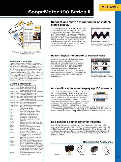
It frequently happens that service are automatically detected andengineers have to spend a lot of adjusted, followed by displayingthe signal in the correct ratiotime adjusting their measuringdevice such as a portable oscilloscopefor an optimal setting. and vertical axis. At least 1.5with respect to the horizontalValuable time is spent completing to 4 periods of the signal arethis set up, and ideally, this could measured before the pattern isbe done automatically.shown.With the introduction of the Connect and View providesnew ScopeMeter 190 Series II, a stable, reliable and repeatabledisplay of virtually anyFluke has revamped its uniquefeature, Connect and View. signal, including motor drive andScope users know how difficulttriggering can be. Wrong ing a button. Signal changes arecontrol signals, without touch-settings show unstable and instantly recognized and settingssometimes wrong results. Fluke’s adjusted for, once again, a stableunique Connect and View display. This is all done automatically,but manual overrulingrecognizes signal patterns, andautomatically sets up correct is still possible. If manual overrulingis needed, the ScopeMetertriggering, attenuator and timebase settings. Switching on the 190 Series will switch from automaticto 1/2 automatic, which isScopeMeter portable oscilloscopeto display correct signal patterns visible on the display.only takes a couple of seconds, Figure 1 gives an example ofand this is exactly what an the different types of waveformsoperator wants.which can de detected bySettings regardingConnect & View. If required the amplitude,criteria for best settings can be AC/DC coupling timebase,optimized by switching on one or Glitch detect triggering,all of the following options: Figure 2 shows the different etc. Automatic triggersettings.Figure 1.From the Fluke Digital Library @ www.fluke.com/library75 ΩScopeMeter 190 Series II® 190 Series IITesting telecommunicationequipment using Pass/Failmask testing with a FlukeScopeMeterG.703 is a standard originaly introduced for voice anddata transmission over digitalnetworks. It an ITU recommendation(formerly CCITT)that’s associated with the PCMstandard. Analog-voice to digitaldataconversion according toPCM requires a bandwidth of64 kb/s (±100 ppm), resulting inthe basic unit for G.703. Throughmultiplexing this results in a T1of 1.544 Mb/s and E1 of2.048 Mb/s.Th electrical characteristicsof the network interfaces aredescribed in recommendationG.703. The signal limits for a2.048 Mb/s signal are shown inFigure 1.The G.703 standardMultiple-channeltesting using twodifferent masksApplication NoteNowadays digital communication systems such as SynchronousDigital Hierarchy (SDH) in Europe and the Synchronous OpticalNetwork (SONET) in North America require standard test methods.The electrical signals are tested agains the standard ITU pulsemasks. The Fluke ScopeMeter 190 Series I portable osci loscopeo fers a standard pass/fail function that can be used to performthese tests. The instrument is capable of storing up to 100 “fails”for further analysis.Demystifyingdrive anomaliesusing the Fluke 190 Series II 2-ChannelScopeMeter ® portable osci loscopeTestingFunctionsCaseStudyFigure 1. G703 - E1 templateA balun is used between thepatch panel and a coaxialtransmission line to match theimpedance of the 120 Ω symmetricalline to a 75 Ω coaxialline. The input and output of thebalun each has it specific mask.The ScopeMeter 190 Series Iportable osci loscopes can simultaneouslyperform a pass/fail testat the input and output of thebalun with di ferent masks.The floating and isolated With FlukeView we can exportinputs of the Fluke ScopeMeter a waveform into a spreadsheet190 Series I test tools make and a custom template can bethese measurements possiblewithout the risk of making using Excel.created by editing a waveformunwanted groundings. Moreover, A reference template forthe high impedance probes a low pass/fail testing can be createdby saving waveforms fromfor direct measurements withoutloading the line and without the FlukeView in .csv format andneed for an external di ferential editing the waveform using, for® Test Toolprobe.Editing the pass/failtemplatesMeasuring tools: 190 Series I2-Channel ScopeMeterOperator: Chris Vogel, HVACTechnician for Siemens BuildingTechnologiesMeasurements: Current and voltagewaveform analysis, power factorTelephoneExchange2 Mb/s120 ΩISDN 30Figure 2. ISDN30 networkApplication NoteConnect the ScopeMetertest tool and view theresult: the start of everymeasurementSeeing is believing? More aptly, seeing isunderstanding.PatchPanelBalun SDHDistr.From the Fluke Digital Library @ www.fluke.com/library2 Mb/s120 ΩIf anyone can wring every last ounce of functionality outof a piece of electronic test equipment, it’s Chris Vogel.At Siemens Building Technologies, Vogel has his work cutout for him keeping HVAC systems running for the company’slarge commercial customers in Florida’s tropicalweather, which is marked by seemingly nonstop 90 °Ftemperatures and 95 % humidity levels. And that’s justone of the cha lenges faced by technicians at SiemensBuilding Technologies, which plays a more sweeping rolein its customers’ success: ensuring energy efficiency,comfort, protection against unauthorized access, andfire safet year-round for every building or office towerentrusted to it by customers.Vogel, an HVAC technician,becomes energized when discussingthe return on investmentIt’s important, says Vogel,in his handheldthat the technician be able toScopeMeter®Test Tool. “Out at one large site,characterize VFD problems bywhere we monitor and troubleshootvariable frequency drivescapturing a waveform from theo fending drive. His premise: A(VFDs), component-level repairsignal is much more te ling whencan often mean the di ferencepresented in a waveform viewbetween a $20 repair part andthan in a single, static voltagereading. The signal has aa $100,000 repair bi l. I knowfirsthand, because we recentlyshape and value that may lookdocumented that very scenario.”right at a glance, but could justOn large VFDs, Vogel uses hisas easily have a distortion orScopeMeter portable osci loscoperough “edge,” or a momentaryto uncover capacitance problems,spike almost too short to betransistor firing mishaps, andseen. Either problem, or a hosteven bleed-throughs on a gate.of other signal anomalies, would“Of course, a transistor is basicaly a lightning-fast switch,”be indistinguishable with just anumeric reading of the signal.he says. “It switches back and“The scope a lows me toforth between open and closed,record information, and from aand it can sometimes start tonumber of sources—sine wavesbreak down. When that happens,on the inputs and outputs ofmotors will start doing weirdVFDs, current and voltage—and,things. For example, at loadfor that matter, make comparisonsof cu rent and voltage sostage we’ l actua ly seethe motor banging back andthat I can derive a power factorforth as if it is not sure whichfor the circuit.”way to turn.”Storing a slice of timeFrom the Fluke Digital Library @ www.fluke.com/library2 Mb/sApplication NoteConnect-and-View triggering for an instant,stable displayIf you’ve used other scopes, you know how trickytriggering can be. If settings are incorrect, resultscan be unstable or incorrect. Connect-and-View automatically sets up correct triggeringby recognizing signal patterns. Without touchinga button, you get a stable, reliable and repeatabledisplay of virtually any signal including motordrive and control signals. It’s especially fast andconvenient when you’re measuring a number oftest points in rapid succession.Connect-and-View captures even themost complex motor drive signals.A range of application notes is available.See the Fluke website.Included AccessoriesFluke 190 Series II 4-channel instruments include a setof four probes, hanging strap, handstrap, USB cable withmini-B connector, double capacity Li-ion battery BP291,battery charger/power adapter BC190, a FlukeView demopackage and users manuals on CD-ROM. The /S-versionsalso include the C290 hard-shell carrying case and theFlukeView software package. The 2-channel models comewith two probes plus a set of TL175 test leads and a singlecapacity battery BP290. The 190-502 also includes twopieces TRM50 coaxial feedthrough terminator.The SCC290 kit includes: C290 hardshell carrying case andFlukeView ® for Windows ® software (full version).Ordering InformationFluke-190-502/S Color ScopeMeter (500 MHz,2 channel), with SCC290-kitFluke-190-204/S Color ScopeMeter (200 MHz,4 channel), with SCC290-kitFluke-190-204 Color ScopeMeter (200 MHz, 4 channel)Fluke-190-202/S Color ScopeMeter (200 MHz,2 channel), with SCC290-kitFluke-190-202 Color ScopeMeter (200 MHz, 2 channel)Fluke-190-104/S Color ScopeMeter (100 MHz,4 channel), with SCC290-kitFluke-190-104 Color ScopeMeter (100 MHz, 4 channel)Fluke-190-062/S Color ScopeMeter (60 MHz,2 channel), with SCC290-kitFluke-190-062 Color ScopeMeter (60 MHz, 2 channel)AS400Probe Accessory Extension set forVPS400 Series probesBP291Double capacity Li-Ion battery(4800 mAh) pack for 190C Series IIBP290Single capacity Li-ion battery(2400 mAh) pack for 190-series IIC195Soft padded carrying case forScopeMeter and accessoriesC290Protective Carrying Case for Fluke190-series IIEBC290External Battery Charger for chargingBP290 or BC291 outside the instrumentHH290Hanging HookRS400Probe Accessory Replacement setfor VPS400 series probesRS500Probe Accessory Replacement setfor VPS510 series probesSCC290 Software and Case kit for Fluke 190Series 190 Series II. Includes SW90Wand C290.SW90WFlukeView ® ScopeMeter Software forWindows ® (full version)TRM50Coaxial 50 Ω feedthrough terminatorVPS410-x Probe-set, 10:1, 1000V CAT III / 600VCAT IV (colors: blue, green, red, grey)VPS420-R Probe-set, bicolor (r/b), 100:1, 150 MHz,1000V CAT III / 600V CAT IV, workingvoltage (voltage between probe tip andreference lead): 2000V CAT III / 1200VCAT IV.VPS510-x Wide bandwidth probeset, 500 MHz,10:1, 600V CAT IIIBuilt-in digital multimeter (2 channel models)190 Series II models with isolated dual inputscope and dedicated digital multimeter.Conveniently switch from waveform analysisto precise multimeter measurements usingthe built in 5000 count digital multimeter.Measurement functions include Vdc, Vac,Vac+dc, resistance, continuity and diode test.Measure current and temperature using suitableshunt, probe or adapter with wide range ofscaling factors.Scope users know how frustrating it is to see a onetimeanomaly flash by, never to be seen again. Notwith the ScopeMeter 190-series! Now you can lookback in time with the touch of a button. In normaluse, the instrument continuously memorizes themost recent 100 screens. At any moment in time, youcan ‘freeze’ these latest screens and scroll throughthem picture-by-picture or replay them as a ‘live’animation. Cursors and zoom can be used for further analysis. You can even usethe advanced trigger capabilities to capture up to 100 specific events. Two sets of 100screens with individual time stamps can be stored for later recall or download to a PC.See dynamic signal behavior instantlyThe digital Persistence mode helps to find anomalies and to analyze complexdynamic signals by showing the waveforms amplitude distribution over time usingmultiple intensity levels and user selectable decay time – it’s as if you’re looking atthe display of an analog, real time oscilloscope! A fast display update rate revealssignal changes instantaneously, useful for instance when making adjustments to asystem under test.SW90WSCC290VPS420-RThe built in multimeter providesconvenient precision measurements.Automatic capture and replay op 100 screensRecommended AccessoriesEBC290AS40083