Controller
Controller
Controller
- No tags were found...

Create successful ePaper yourself
Turn your PDF publications into a flip-book with our unique Google optimized e-Paper software.
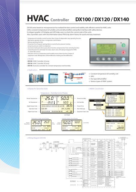
HVAC<strong>Controller</strong>DX100 / DX120 / DX140DX100 series based on microprocessor has realized the best control and stability with efficient control for HVAC units(AHU, constant temperature & humidity unit and dehumidifier) and perfect interface with safety devices.Its elegant graphic LCD display and LED helps users to check the current state of the units.Also, it provides users with the information about PM & trip alarm history for quick and easy treatment.- Temperature & humidity control function, Max. 6 loop of independent step operating function- Alternative operation by max. 4 compressors and 8 heaters- Backup operating function- Prevention from frequent starting failure occurred by low pressure huntingusing low pressure switch in compressor- Successive starting function, pump down function and prevention from restarting function- Control function for cold water, hot water, steam valve, SCR, damper designed for HVAC(4~20mA PID control)- Detection of error in temperature and humidity sensor, Alarm function, Output ofequipment state (Refrigeration, Dehumidification, Heating and Humidification)ㅁModels- DX100 : HVAC <strong>Controller</strong> (2Comp)- DX120 : HVAC <strong>Controller</strong> (4Comp)- DX140 : Exclusive controller for constant temperature and humidityㅁApplicationsExhaust AirSupply AirReturn AirOutside Airㅇ Constant temperature & humidity unitㅇ AHUㅇ Dry type dehumidifierㅇ Various types of HVAC systemㅁDisplay for Operation StateㅁMENU ConstitutionPresent TemperatureSet TemperatureDigital Output StateOperation StateDigital Input StateTemperature + Humidity Control DisplayPVSP25.025.050.0C PV%SPCM1 SL1 CM2 SL2 H1 H2 H3 H4 H5 HUD ALR BROLOC STPC1A LP1 LP2 C2A RHA AFS HUA BRA RET50.008:20DPS. ALARM08Lock SignalPresent HumiditySet HumidityPresent TimeAlarm MessageEquipment State CodeMENU SELECTRUN INFOOPERATIONSCHEDULETRIP LOGOPERATION▶ SET TEMPERATURE : 25.0 ℃SET HUMIDITY : 50.0 %COOL DIFFERENCE : 200 PaHEAT DIFFERENCE : 120 ℃DEHUMIDITY DIFF : 1.0 ℃TRIP LOG00 080102 15:55 FIRST POWER ON01 080102 16:10 FAN FAULT02 080102 16:30 COMP#1 FAULT03 080102 16:30 COMP#2 FAULT04 080102 16:45 X HEATER FAULTTemperature Single Control DisplayHumidity Single Control DisplayPresentTemperatureC SP25.0 25.0PVCM1 SL1 CM2 SL2 H1 H2 H3 H4 H5 ALR BRO08:20LOC STPSTAND BYC1A LP1 LP2 C2A RHA AFS BRA RET 08CSetTemp.CurrentHumidity% SP50.0 50.0PVCM1 SL1LOCSTPCM2 SL2C1A LP1 LP2 C2AAFSHUAHUD ALR BROBRA RET%08:20STAND BY08Set HumidityTRIP LOG STATECOMP#1 FAULT ON 080102 16:30TEMO : -20.0℃ HUM : 15.0%ID (10~1):N (12~1):ㅁWiring Diagram (DX100)SURGEABSORBERNOISEFILTER100AC TRANSFORMERAC 220V / 24V, 50VAG0 (NEUTRAL)UIC DX100 Series <strong>Controller</strong>TERMINALDESC.NOJ1 - 1J1 - 2J1 - 3FGG0GLEGEND24VAC 50/60HzCONTROLLERPOWER INPUTLEGENDCOMPRESSOR #1ON/OFF CONTROLMAIN SOL #1ON/OFF CONTROLCOMPRESSOR #2ON/OFF CONTROLDESC. TERMINAL NON1 J21 - 1N2J21 - 2N3J21 - 3COMP1COMP2AC 220V, 50/60Hzafter Noise filter Output TerminalSOL1100200FUSE3AAC 220V50/60Hz250VAC 5A200G (HOT)FUSE3ARH+RH-TH1TH2(1)RH & TEMP TRANSMITTERCompressor #1 AlarmLP Switch for Comp #1Sheild WireJ11 - 1 +24VJ11 - 2 B4J11 - 3 B5J11 - 4 AVSSJ12 - 1 B1J12 - 2 AVSSJ12 - 3 B2J12 - 4 AVSSJ12 - 5 B3RH INPUT(4~20mA)TEMP INPUT(4~20mA)TEMP INPUT-10 ~ 100 ℃SPARE TEMPReact Heater Temp-20 ~ 200℃J13 - 1 ID1 COMP#1 ALARMJ13 - 2 ID2 COMP#1 LPSMAIN SOL #2ON/OFF CONTROLOUTPUT COMMON 1RE-HEATER #1ON/OFF CONTROLRE-HEATER #2ON/OFF CONTROLMULTI-FUNCTIONON/OFF CONTROLMULTI-FUNCTIONON/OFF CONTROLOUTPUT COMMON 2N4C1N5N6N3N8C2J21 - 4J21 - 5J22 - 1J22 - 2J22 - 3J22 - 4J22 - 5RH1N7SOL2RH2N8Compressor #2 AlarmJ13 - 3ID3COMP#2 ALARMMULTI-FUNCTIONON/OFF CONTROLN9J23 - 1N9LP Switch for Comp #2J13 - 4ID4COMP#2 LPSMULTI-FUNCTIONON/OFF CONTROLN10J23 - 2N10Halon, Smog DetectorReact Fan OCRG (HOT)J13 - 5J13 - 6ID5IDCM1Halon, Smog DetectorReact-Fan AlarmID COMMONMULTI-FUNCTIONON/OFF CONTROLBROWER (Pump)ON/OFF CONTROLN11N12J23 - 3J23 - 4N11BWRRe-Heater AlarmFlow SWHumidifier AlarmBrower(Pump) Over CurrentRemote SignalMMI CONNECTIONRS-485 (MODBUS)EXTENTION BOARDG (HOT)J14 - 1J14 - 2J14 - 3J14 - 4J14 - 5J14 - 6ID6ID7ID8ID9ID10* Optional Spec.TB1 - 1 SGTB1 - 2 BTB1 - 3 A* Optional Spec.TB2 - 1 SGTB2 - 2 BTB2 - 3 AIDCM2RE-HEATER OTFlow S/WHUMIDIFY ALARMBROWER OCRREMOTE ON/OFFID COMMONSYSTEM BUS RS485LOCAL BUS RS485OUTPUT COMMON 3C3J23 - 5* Optional Spec.MULTI-FUNCTION Y1J6 - 1ANALOG#1(4~20mA) YG1J6 - 2MULTI-FUNCTION Y2J6 - 3ANALOG#2(4~20mA) YG2J6 - 4MULTI-FUNCTION Y3J6 - 5ANALOG#3(4~20mA) YG3J6 - 6* MULTI-FUNCTION CONTROL (Selctable user)PID ANALOG #1~3 DIGITAL ON/OFF(N7~N11)1. Cool & Dehumid 1. Heater #3~#72.Cool Control2. Humidifier #1~#43. Dehumid. Control 3. Total alarm4. Error (Over/Under Range)4. Heat Control5. React Fan5. Diff. Press Control6. React Heater #1~#47. Temperature Retrans. 7. Run/Stop State8. Humidity Retrans. 8. Cool State9. Diff. Retrans.9. Heat State10. Dehumidify State11. Humidify State※ Shield Wire UseConnection Frame and BuildingGround+-+-+-


![[EN] - PLANETELF ACD 220 - 2004-07-09 - Yukselteknik.com](https://img.yumpu.com/35424424/1/184x260/en-planetelf-acd-220-2004-07-09-yukselteknikcom.jpg?quality=85)

![[EN] - LUNARIA SK 100 - 2006-12-13 - Yukselteknik.com](https://img.yumpu.com/30899966/1/184x260/en-lunaria-sk-100-2006-12-13-yukselteknikcom.jpg?quality=85)
![[EN] - PLANETELF ACD 68 - 2007-02-14](https://img.yumpu.com/30624511/1/184x260/en-planetelf-acd-68-2007-02-14.jpg?quality=85)