

The SpaceX Falcon 1 Launch Vehicle Flight 3 - International ...
The SpaceX Falcon 1 Launch Vehicle Flight 3 - International ...
The SpaceX Falcon 1 Launch Vehicle Flight 3 - International ...

Create successful ePaper yourself
Turn your PDF publications into a flip-book with our unique Google optimized e-Paper software.
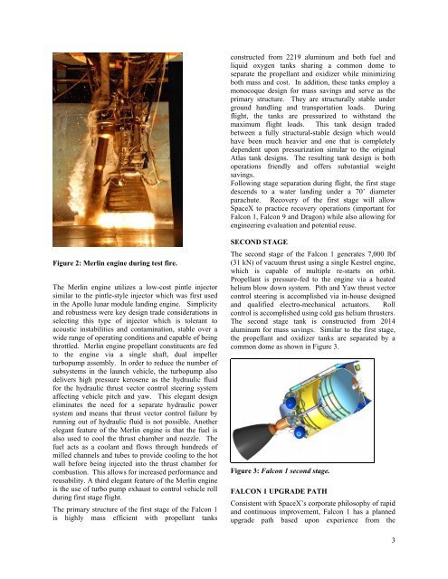
Figure 2: Merlin engine during test fire.<br />
<strong>The</strong> Merlin engine utilizes a low-cost pintle injector<br />
similar to the pintle-style injector which was first used<br />
in the Apollo lunar module landing engine. Simplicity<br />
and robustness were key design trade considerations in<br />
selecting this type of injector which is tolerant to<br />
acoustic instabilities and contamination, stable over a<br />
wide range of operating conditions and capable of being<br />
throttled. Merlin engine propellant constituents are fed<br />
to the engine via a single shaft, dual impeller<br />
turbopump assembly. In order to reduce the number of<br />
subsystems in the launch vehicle, the turbopump also<br />
delivers high pressure kerosene as the hydraulic fluid<br />
for the hydraulic thrust vector control steering system<br />
affecting vehicle pitch and yaw. This elegant design<br />
eliminates the need for a separate hydraulic power<br />
system and means that thrust vector control failure by<br />
running out of hydraulic fluid is not possible. Another<br />
elegant feature of the Merlin engine is that the fuel is<br />
also used to cool the thrust chamber and nozzle. <strong>The</strong><br />
fuel acts as a coolant and flows through hundreds of<br />
milled channels and tubes to provide cooling to the hot<br />
wall before being injected into the thrust chamber for<br />
combustion. This allows for increased performance and<br />
reusability. A third elegant feature of the Merlin engine<br />
is the use of turbo pump exhaust to control vehicle roll<br />
during first stage flight.<br />
<strong>The</strong> primary structure of the first stage of the <strong>Falcon</strong> 1<br />
is highly mass efficient with propellant tanks<br />
constructed from 2219 aluminum and both fuel and<br />
liquid oxygen tanks sharing a common dome to<br />
separate the propellant and oxidizer while minimizing<br />
both mass and cost. In addition, these tanks employ a<br />
monocoque design for mass savings and serve as the<br />
primary structure. <strong>The</strong>y are structurally stable under<br />
ground handling and transportation loads. During<br />
flight, the tanks are pressurized to withstand the<br />
maximum flight loads. This tank design traded<br />
between a fully structural-stable design which would<br />
have been much heavier and one that is completely<br />
dependent upon pressurization similar to the original<br />
Atlas tank designs. <strong>The</strong> resulting tank design is both<br />
operations friendly and offers substantial weight<br />
savings.<br />
Following stage separation during flight, the first stage<br />
descends to a water landing under a 70’ diameter<br />
parachute. Recovery of the first stage will allow<br />
<strong>SpaceX</strong> to practice recovery operations (important for<br />
<strong>Falcon</strong> 1, <strong>Falcon</strong> 9 and Dragon) while also allowing for<br />
engineering evaluation and potential reuse.<br />
SECOND STAGE<br />
<strong>The</strong> second stage of the <strong>Falcon</strong> 1 generates 7,000 lbf<br />
(31 kN) of vacuum thrust using a single Kestrel engine,<br />
which is capable of multiple re-starts on orbit.<br />
Propellant is pressure-fed to the engine via a heated<br />
helium blow down system. Pith and Yaw thrust vector<br />
control steering is accomplished via in-house designed<br />
and qualified electro-mechanical actuators. Roll<br />
control is accomplished using cold gas helium thrusters.<br />
<strong>The</strong> second stage tank is constructed from 2014<br />
aluminum for mass savings. Similar to the first stage,<br />
the propellant and oxidizer tanks are separated by a<br />
common dome as shown in Figure 3.<br />
Figure 3: <strong>Falcon</strong> 1 second stage.<br />
FALCON 1 UPGRADE PATH<br />
Consistent with <strong>SpaceX</strong>’s corporate philosophy of rapid<br />
and continuous improvement, <strong>Falcon</strong> 1 has a planned<br />
upgrade path based upon experience from the<br />
3