SCAL Designer
SCAL Designer
SCAL Designer
- No tags were found...

You also want an ePaper? Increase the reach of your titles
YUMPU automatically turns print PDFs into web optimized ePapers that Google loves.
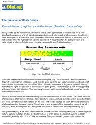
Archive TemplateThe <strong>Designer</strong> tier provides the user with the tools necessary to design a <strong>SCAL</strong> preparation andanalytical programme that is fit for purpose. The aforementioned truth tables encompass reservoirtype, reservoir lithologies, project objectives and executed downhole logs, and operate within aWizard function. The highlighting of appropriate items on panels that interface with the tables drivesan elimination and selection process that suggests a suitable agenda. The generation of theprogramme can be automatic, once key data points are completed, with in-built defaults providingthe preferred measurement sequence and number of samples. Alternatively there are opportunitiesto input personal or company preferences that control and shape the final programme.Figure 2. Screen Images from the <strong>SCAL</strong> <strong>Designer</strong>The programme generated by the Design Wizard can in turn be validated by the Report Wizard.The validation is in two parts: flagged lithologies and required parameter generation. For eachlithology a number of flags are presented, which inform the user of areas of concern that must beaddressed. For example, in unconsolidated sands hysteresis linked to the repeated use of anelevated overburden pressure must be avoided by following the multiple sample suite approachdescribed in the sample preparation component of <strong>SCAL</strong> Guru.Table 1Flagged Lithology – Unconsolidated Sand●●●●●●Core Condition. The user should be aware that the core must have been stabilized at wellsite by one ofthe three commercially available methods, i.e. resin, foam or gypsum. Alternatively the core may havebeen frozen to prevent slumping, fracturing, etc. However, this method can disrupt grain to grainrelationships, due to the expansion of the pore fluids. Without physical support, changes to the pore systemcan prevent the generation of representative data.Pre-Screening. Prior to cutting the liner for geological examination and the selection of sampling points,the use of CT Scanning is recommended. Bedding and other structural features can be identified, rubblesections, void spaces and artefacts such as pyrite nodules avoided, and slumping, fracturing and localizedcollapse accounted for.Sample Size. The lack of adequate cementation generally limits the size of the samples to be tested toplugs of 1 or 1.5 inches in diameter.Sample Mounting. To provide a right cylinder for testing purposes requires the sand to be plunge cut orrotary drilled (if frozen), and mounted in heat shrink PTFE tubing with a pair of steel gauzes over each endface. A mounted plug can be used for the full range of <strong>SCAL</strong> testing.Sample Preparation. As the grains may move or rotate under adverse conditions, the use of the extendedflush cleaning regime or the repeated refluxing of a soxhlet extractor can be damaging. It is recommendedthat the benign Corex Constant Immersion-Constant Replenishment system of cleaning be employed. Thistechnique does not promote liquid flow but cleans through the removal of contaminants by gentle diffusion.Establishment of Base Parameters and Assignment of a Multi Suite System of Testing.Unconsolidated sand is liable to hysteresis caused by the repeated application of an overburden pressure.It is preferable to measure the base parameters of gas permeability and porosity at a nominal pressure offile:///D|/Documents%20and%20Settings/doddnigr/My%...s/archive/cornwall_scal_designer/scal_designer.htm (2 of 4) [04/08/2003 10:36:42]