xs650se supplement - Knucklebuster
xs650se supplement - Knucklebuster
xs650se supplement - Knucklebuster
- No tags were found...

Create successful ePaper yourself
Turn your PDF publications into a flip-book with our unique Google optimized e-Paper software.
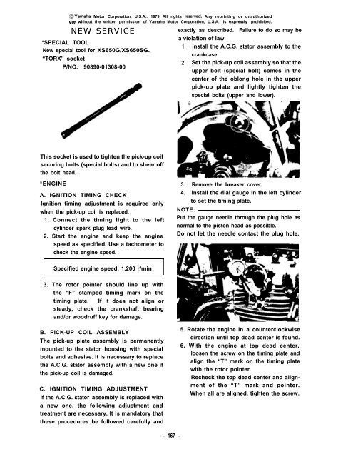
~Yamaha Motor Corporation, U.S.A.. 1979 All rights reoened. Any reprinting or unauthorizeduse without the written permission of Yamaha Motor Corporation, U.S.A., is expressly prohibited.NEW SERVICE*SPECIAL TOOLNew special tool for XS650G/XS650SG.“TORX” socketP/NO. 90890-01308-00exactly as described. Failure to do so may bea violation of law.1. Install the A.C.G. stator assembly to thecrankcase.2. Set the pick-up coil assembly so that theupper bolt (special bolt) comes in thecenter of the oblong hole in the upperpick-up plate and lightly tighten thespecial bolts (upper and lower).This socket is used to tighten the pick-up coilsecuring bolts (special bolts) and to shear offthe bolt head.*ENGINEA. IGNITION TIMING CHECKIgnition timing adjustment is required onlywhen the pick-up coil is replaced.1. Connect the timing light to the leftcylinder spark plug lead wire.2. Start the engine and keep the enginespeed as specified. Use a tachometer tocheck the engine speed.3. Remove the breaker cover.4. Install the dial gauge in the left cylinderto set the timing plate.NOTE:Put the gauge needle through the plug hole asnormal to the piston head as possible.Do not let the needle contact the plug hole.Specified engine speed: 1,200 r/minI3. The rotor pointer should line up withthe “F” stamped timing mark on thetiming plate. If it does not align orsteady, check the crankshaft bearingand/or woodruff key for damage.B. PICK-UP COIL ASSEMBLYThe pick-up plate assembly is permanentlymounted to the stator housing with specialbolts and adhesive. It is necessary to replacethe A.C.G. stator assembly with a new one ifthe pick-up coil is damaged.C. IGNITION TIMING ADJUSTMENTIf the A.C.G. stator assembly is replaced witha new one, the following adjustment andtreatment are necessary. It is mandatory thatthese procedures be followed carefully and5. Rotate the engine in a counterclockwisedirection until top dead center is found.6. With the engine at top dead center,loosen the screw on the timing plate andalign the “T” mark on the timing platewith the rotor pointer.Recheck the top dead center and alignmentof the “T” mark and pointer.When all are aligned, tighten the screw.- 167 -