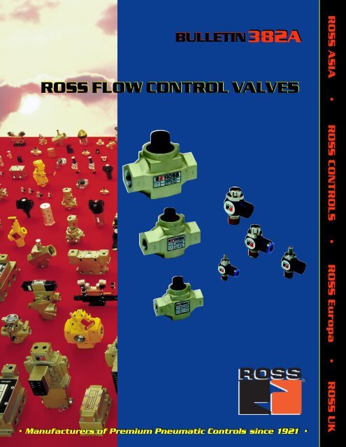
ROSS FLOW CONTROL VALVES
ROSS FLOW CONTROL VALVES
ROSS FLOW CONTROL VALVES

Create successful ePaper yourself
Turn your PDF publications into a flip-book with our unique Google optimized e-Paper software.
• •• •
Compact, Low Profile Flow Control Valves<strong>ROSS</strong> flow control valves provide high air flow ratesinto a cylinder, and precisely controlled flow rates outof the cylinder. The adjustable flow can range fromnear zero to full flow.Selecting flow control valveswith sufficient flow capacityis important so that they donot become the limiting factorin the cylinder controlsystem. Full flow capacityshould match that of the controlvalve to keep cylinder motionsmooth and predictable in both directions.FullControlled Flow Rate0TYPICAL PERFORMANCE CURVENo. of Turns from 0to Maximum Flow1/4, 3/8 . . . 141/2, 3/4 . . . 121, 1-1/4 . . . 24Turns of Adjustment KnobLarge knob for easy hand adjustment.Turn clockwise to reduce controlledflow.Compact size,low profile.Long thread engagementgives precise adjustment.Brass stem gives visible indication offlow rate in controlled direction (port2 to 1).Non- rising adjustmentknob.High flow capacity in free-flow direction(port 1 to 2). Same high flowavailable in reverse direction.Positive locking. Prevents changeof adjustment knob due to vibrationor tampering.Port numbers cast intobody match flow symbols onnametag.Port 2Port 1Available with port sizes 1/4,3/8, 1/2, 3/4, 1, and 1-1/4.Durable cast-aluminum body.Combination check poppetand metering device.Large wrench flatsaround each port.Dirt-tolerant poppet design. Available in alternatematerials for extreme temperature applications.Port Avg. Cv Valve Model Dimensions inches (mm)Size (Full Flow) Number* A B C1/4 2.3 1968E2007 2.8 (70) 1.3 (32) 2.4 (60)3/8 2.6 1968E3007 2.8 (70) 1.3 (32) 2.4 (60)1/2 7.5 1968E4007 3.8 (96) 1.6 (40) 3.2 (82)3/4 8.3 1968E5007 3.8 (96) 1.6 (40) 3.2 (82)1 17 1968E6007 5.0 (127) 2.5 (64) 4.5 (113)1-1/4 22 1968E7007 5.0 (127) 2.5 (64) 4.5 (113)*NPT threads. To order G threads, precede the model number by “D.”C2 1BASTANDARD SPECIFICATIONSAmbient/Media Temperature: 40 o to 175 o F(4 o to 80 o C).Flow Media: Filtered air.Inlet Pressure: 5 to 150 psig (0.3 to 10 bar).2
<strong>ROSS</strong> Flow Control Valves- 1/8” to 2 1/2” Port Sizes21CBASTANDARD SPECIFICATIONSAmbient/Media Temperature: 40 o to175 o (4 o to 80 o C).Flow Media: Filtered air.Inlet Pressure: 5 to 150 psig (0.3 to10 bar).Port Avg. Cv Valve Model Dimensions inches (mm)Size (Full Flow) Number* A B C1/8 0.5 1968D1004 2.4 (62) 1.3 (32) 1.0 (25)1/4 0.5 1968D2004 2.4 (62) 1.3 (32) 1.0 (25)3/8 0.5 1968D3014 3.7 (67) 1.6 (41) 1.2 (29)*NPT threads. To order G threads, precede the model number by “D.”BCA21Port Avg. Cv Valve Model Dimensions inches (mm)Size (Full Flow) Number* A B C1/4 2.3 1968B2007 3.5 (89) 1.3 (32) 4.3 (108)3/8 2.6 1968B3007 3.5 (89) 1.3 (32) 4.3 (108)1/22.6 1968B4017 3.5 (89) 1.3 (32) 4.3 (108)7.5 1968B4007 4.8 (121) 1.8 (45) 5.6 (142)3/4 8.3 1968B5007 4.8 (121) 1.8 (45) 5.6 (142)18.3 1968B6017 4.8 (121) 1.8 (45) 5.6 (142)17 1968B6007 5.4 (137) 2.3 (57) 7.1 (181)1-1/4 22 1968B7007 5.4 (137) 2.3 (57) 7.1 (181)STANDARD SPECIFICATIONSAmbient/Media Temperature: 40 o to175 o F (4 o to 80 o C).Flow Media: Filtered air.Inlet Pressure: 5 to 150 psig (0.3 to10 bar).1-1/222 1968B8017 5.4 (137) 2.3 (57) 7.1 (181)50 1968B8007 7.5 (191) 3.5 (90) 9.5 (241)2 50 1968B9007 7.5 (191) 3.5 (90) 9.5 (241)2-1/2 50 1968B9017 7.5 (191) 3.5 (90) 9.5 (241)*NPT threads. To order G threads, precede the model number by “D.”www.rosscontrols.com 3
Right-Angle Flow Control ValvesCompact, durable and versatile <strong>ROSS</strong> right-angle flow control valve screws directly into cylinder port. Inlet portcan then be swiveled 360 o for optimum placement. Versatile model lineup allows controlled flow to be set eitherby a screwdriver slot or by a knurled knob. Inlet ports are available in either threaded or with push-on fittings.O-ring seals on adjusting stemprovide friction to keep stem inits set position.Accessible wrench flatssimplify installation.Models available with flow adjustmentby screw-driver slot or knurled knob (dottedline). Turn clockwise to reduce controlledflow.Nickel-plated brassstem construction.Anodized aluminumbody.Inlet is a swivel port thatcan be rotated 360 o for optimumport placement.CBO-ring seals provideleak-free sealing for thevalve body.Threads precoatedwith pipe sealant.Compact design, threads directlyinto cylinder ports.Models available with1/8, 1/4, 3/8, or 1/2 NPTor G threads.Models available with1/4 or 3/8 tube fittings.Removable tubing release ring.Port orValve Model Number*Tube O.D. Avg. Cv Type of Threaded Tube Dimensions inches (mm)Size (Full Flow) Adjustment Inlet Fitting A B C1/8 0.31/4 0.63/8 1.91/2 2.8ASlot 1968A1008 1968A1108** 1.0 (27) 1.3 (32) 0.6 (15)Knob 1968A1018 1968A1118** 1.0 (27) 1.3 (32) 0.6 (15)Slot 1968A2008 1968A2108 1.3 (33) 1.6 (41) 0.8 (19)Knob 1968A2018 1968A2118 1.3 (33) 2.2 (56) 0.8 (19)Slot 1968A3008 1968A3108 1.6 (41) 2.6 (66) 0.9 (23)Knob 1968A3018 1968A3118 1.5 (41) 3.0 (77) 0.9 (23)Slot 1968A4008 --- 1.8 (46) 2.3 (58) 1.1 (28)Knob 1968A4018 --- 1.8 (46) 3.2 (80) 1.1 (28)*NPT threads. To order G threads, precede the model number by “D.” ** These models have 1/8 threaded inlet, but with 1/4 tube fittings.FullTYPICAL PERFORMANCE CURVESTANDARD SPECIFICATIONSAmbient/Media Temperature:40 o to 175 o F (4 o to 80 o C).Flow Media: Filtered air.Inlet Pressure: 5 to 150 psig (0.3 to 10 bar).21Controlled Flow Rate0No. of Turns from 0to Maximum Flow1/8 . . . . 91/4, 1/2 . . . . 83/8 . . . 10Turns of Adjustment Knob4
CAUTIONSPRE-INSTALLATION or SERVICE1. Before servicing a valve or other pneumatic component, besure that the electrical supply is turned off and that the entirepneumatic system is shut off and exhausted.2. All <strong>ROSS</strong> products, including service kits and parts, should beinstalled and/or serviced only by persons having training and experiencewith pneumatic equipment. Because any installation canbe tampered with or need servicing after installation, persons responsiblefor the safety of others or the care of equipment mustcheck every installation on a regular basis and perform all necessarymaintenance.3. All applicable instructions should be read and complied withbefore using any fluid power system in order to prevent harm topersons or equipment. In addition, overhauled or serviced valvesmust be functionally tested prior to installation and use.4. Each <strong>ROSS</strong> product should be used within its specificationlimits. In addition, use only <strong>ROSS</strong> parts to repair <strong>ROSS</strong> products.Failure to follow these directions can adversely affect the performanceof the product or result in the potential for human injury.FILTRATION and LUBRICATION5. Dirt, scale, moisture, etc. are present in virtually every air system.Although some valves are more tolerant of these contaminantsthan others, best performance will be realized if a filter isinstalled to clean the air supply, thus preventing contaminantsfrom interfering with the proper performance of the equipment.<strong>ROSS</strong> recommends a filter with a 5-micron rating for normal applications.6. All standard <strong>ROSS</strong> filters and lubricators with polycarbonateplastic bowls are designed for compressed air applications only.Do not fail to use the metal bowl guard, where provided, to minimizedanger from high pressure fragmentation in the event ofbowl failure. Do not expose these products to certain fluids, suchas alcohol or liquefied petroleum gas, as they can cause bowls torupture, creating a combustible condition, hazardous leakage, andthe potential for human injury. Immediately replace a crazed,cracked, or deteriorated bowl. When bowl gets dirty, replace it orwipe it with a clean dry cloth.7. Only use lubricants which are compatible with materials usedin the valves and other components in the system. Normally, compatiblelubricants are petroleum base oils with oxidation inhibitors,an aniline point between 82 degrees Celsius (180 degrees Fahrenheit)and 104 degrees Celsius (220 degrees Fahrenheit), and anISO 32, or lighter, viscosity. Avoid oils with phosphate type additiveswhich can harm polyurethane components, potentially leadingto valve failure and/or human injury.AVOID INTAKE/EXHAUST RESTRICTION8. Do not restrict the air flow in the supply line. To do so couldreduce the pressure of the supply air below the minimum requirementsfor the valve and thereby cause erratic action.9. Do not restrict a poppet valve’s exhaust port as this can adverselyaffect its operation. Exhaust silencers must be resistent toclogging and have flow capacities at least as great as the exhaustcapacities of the valves. Contamination of the silencer can result inreduced flow and increased back pressure.<strong>ROSS</strong> expressly disclaims all warranties and responsibility for anyunsatisfactory performance or injuries caused by the use of thewrong type, wrong size, or inadequately maintained silencer installedwith a <strong>ROSS</strong> product.POWER PRESSES10. Mechanical power presses and other potentially hazardousmachinery using a pneumatically controlled clutch and brake mechanismmust use a press control double valve with a monitoring device.A double valve without a self-contained monitoring deviceshould be used only in conjunction with a control system whichassures monitoring of the valve. All double valve installations involvinghazardous applications should incorporate a monitoringsystem which inhibits further operation of the valve and machine inthe event of a failure within the valve.ENERGY ISOLATION/EMERGENCY STOP11. Per specifications and regulations, <strong>ROSS</strong> L-O-X ® and L-O-X ® /EEZ-ON ® products are defined as energy isolation devices, NOTAS EMERGENCY STOP DEVICES.WARRANTYProducts manufactured by <strong>ROSS</strong> are warranted to be free of defects in material and workmanship for a period of one year fromthe date of purchase. <strong>ROSS</strong>’ obligation under this warranty is limited to repair or replacement of the product or refund of thepurchase price paid solely at the discretion of <strong>ROSS</strong> and provided such product is returned to <strong>ROSS</strong> freight prepaid and uponexamination by <strong>ROSS</strong> is found to be defective. This warranty shall be void in the event that product has been subject to misuse,misapplication, improper maintenance, modification or tampering. THE WARRANTY EXPRESSED ABOVE IS IN LIEU OF ANDEXCLUSIVE OF ALL OTHER WARRANTIES AND <strong>ROSS</strong> EXPRESSLY DISCLAIMS ALL OTHER WARRANTIES EITHER EX-PRESSED OR IMPLIED WITH RESPECT TO MERCHANTABILITY OR FITNESS FOR A PARTICULAR PURPOSE. <strong>ROSS</strong> MAKESNO WARRANTY WITH RESPECT TO ITS PRODUCTS MEETING THE PROVISIONS OF ANY GOVERNMENTAL OCCUPA-TIONAL SAFETY AND/OR HEALTH LAWS OR REGULATIONS. IN NO EVENT SHALL <strong>ROSS</strong> BE LIABLE TO PURCHASER,USER, THEIR EMPLOYEES OR OTHERS FOR INCIDENTAL OR CONSEQUENTIAL DAMAGES WHICH MAY RESULT FROM ABREACH OF THE WARRANTY DESCRIBED ABOVE OR THE USE OR MISUSE OF THE PRODUCTS. NO STATEMENT OF ANYREPRESENTATIVE OR EMPLOYEE OF <strong>ROSS</strong> SHALL EXTEND THE LIABILITY OF <strong>ROSS</strong> AS SET FORTH HEREIN.www.rosscontrols.com 5
P.O. Box 7015Troy, Michigan 48007 U.S.A.Telephone (00) 1-248-764-1800FAX (00) 1-248-764-1850www.rosscontrols.comIn the United States:Customer Service- 1-800-GET-<strong>ROSS</strong>Technical Service- 1-888-TEK-<strong>ROSS</strong><strong>ROSS</strong>/FLEX ® Service- 1-888-<strong>ROSS</strong>-FLXRobert-Bosch-Strae 2D-63225 Langen, GermanyTelephone (011) 49-6103-7597-0FAX (011) 49-6103-7469-410209-5 Tana, Sagamihara-shiKanagawa 229-1124, JapanTelephone (011) 81-427-78-7251FAX (011) 81-427-78-7256St. James Road, BrackleyNorthamptonshire NN13 7XYUnited KingdomTelephone (011) 44-1280-706668FAX (011) 44-1280-705630Printed in the U.S.A. - Rev. 6/98 © Copyright 1998, Form A10109