

Pass-Reject Cavity & Duplexer Tuning - Telewave, Inc.
Pass-Reject Cavity & Duplexer Tuning - Telewave, Inc.
Pass-Reject Cavity & Duplexer Tuning - Telewave, Inc.

You also want an ePaper? Increase the reach of your titles
YUMPU automatically turns print PDFs into web optimized ePapers that Google loves.
PASS-REJECT CAVITY AND DUPLEXER TUNING<br />
IMPORTANT:<br />
All cavities and cavity-based devices are factory tuned to the exact frequencies indicated<br />
on the label. No further tuning or optimization is necessary. If frequency or insertion loss<br />
must be changed, <strong>Telewave</strong> recommends that the equipment be returned to the factory<br />
to ensure optimum performance. The instructions in this document are for use only if<br />
factory service is not practical.<br />
TEST EQUIPMENT MINIMUM REQUIREMENTS:<br />
1. Calibrated RF signal generator with 0 dBm output.<br />
2. Calibrated frequency counter or meter.<br />
3. Calibrated RF indicator such as a network analyzer or spectrum analyzer,<br />
with sensitivity of at least 80 dB below the RF generator output.<br />
Tools required: 7/16" wrench and nut-driver, medium and small fl at-blade screwdrivers.<br />
NOTE: When transmitter power is passing through a cavity, high RF voltages and currents exist on the<br />
internal surfaces. <strong>Cavity</strong> tuning should be performed using a signal generator only. If no other RF<br />
source is available, use the lowest output power available and make only minimal adjustments.<br />
1. TUNING THE PASS FREQUENCY<br />
A. Adjust the signal generator to the desired<br />
pass frequency at 0 dBm output.<br />
B. Connect the signal generator to one side of<br />
the cavity "T" connector, and the monitor or<br />
analyzer to the other side.<br />
C. Loosen the 7/16" locking nut on the center<br />
tuning shaft, and tune the shaft of the cavity<br />
for maximum response as indicated on<br />
the analyzer.<br />
2. TUNING THE REJECT FREQUENCY<br />
A. Adjust the signal generator to the desired<br />
reject frequency at 0 dBm output.<br />
B. Connect the signal generator to one side of<br />
the cavity "T" connector, and the monitor or<br />
analyzer to the other side.<br />
C. Tune the capacitor for maximum attenuation<br />
of the output signal, as indicated on the<br />
analyzer.<br />
<strong>Telewave</strong>, <strong>Inc</strong>. San Jose, CA 1-800-331-3396 ~ 408-929-4400 www.telewave.com<br />
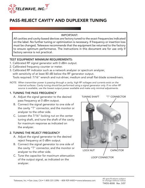
TUNING SHAFT "T" CONNECTOR<br />
LOCK NUT CAPACITOR<br />
LOOP CONNECTOR<br />
All specifications subject<br />
to change without notice<br />
TWDS-8008 Rev. 3/07
PASS-REJECT CAVITY AND DUPLEXER TUNING<br />
3. INSERTION LOSS ADJUSTMENT<br />
A. Adjust the signal generator to the desired pass frequency at 0 dBm output.<br />
B. Loosen the three retaining screws around the loop connector. Rotate the loop<br />
until the analyzer indicates the desired insertion loss. Tighten the retaining screws,<br />
and repeat Steps 1 and 2. An increase in the insertion loss will also increase the<br />
attenuation at the reject frequency. Minimum insertion loss occurs when the<br />
capacitor is on the opposite side of the connector, away from the center tuning rod.<br />
NOTE: All tuning adjustments are mutually dependent. This means that when you adjust the capacitor, the<br />
insertion loss will change and the loop position may have to be readjusted. The center tuning may<br />
have changed as well. Multiple adjustments will be required to achieve the best performance.<br />
4. PASS-REJECT DUPLEXER TUNING PROCEDURE<br />
A. Examine the labels on the top of the duplexer, and locate the TX and RX ports. The<br />
cavity set for TX will be PASS-TX and REJECT-RX. The cavity set for RX will be PASS-RX<br />
and REJECT-TX. If TX and RX are not marked, then you must determine which port<br />
is connected to the lower frequency device, and which is connected to the higher<br />
frequency device. The cavity set for the low frequency device will be PASS-LOW and<br />
REJECT-HIGH. The cavity set for the high frequency device will be PASS-HIGH and<br />
REJECT-LOW.<br />
B. Tune one cavity at a time using Steps 1-3. The reject frequency of one set of cavities<br />
is always tuned to the pass frequency of the other set.<br />
RECEIVER<br />
TRANSMITTER<br />
Tune rejection on these cavities to TX frequency<br />
Tune rejection on these cavities to RX frequency<br />
<strong>Telewave</strong>, <strong>Inc</strong>. San Jose, CA 1-800-331-3396 ~ 408-929-4400 www.telewave.com<br />
ANTENNA<br />
All specifications subject<br />
to change without notice<br />
TWDS-8008 Rev. 3/07