Ceiling Microphone Array Installation Manual - Rev.1.3 - ClearOne
Ceiling Microphone Array Installation Manual - Rev.1.3 - ClearOne
Ceiling Microphone Array Installation Manual - Rev.1.3 - ClearOne
- No tags were found...

Create successful ePaper yourself
Turn your PDF publications into a flip-book with our unique Google optimized e-Paper software.
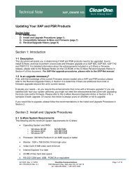
<strong>Ceiling</strong> <strong>Microphone</strong> <strong>Array</strong>INSTALLATION MANUAL
<strong>Installation</strong>PHYSICAL CHARACTERISTICS<strong>Microphone</strong> <strong>Array</strong> Dimensions (Excluding Cables and Mounting)Length: 3.3 in (8.38 cm)Diameter: 1.5 in (3.81 cm)CABLESTwo cables and a mixer adapter are used for connecting from the microphone array throughthe pass-through Mounting Assembly to the mixer.• One 4-pin mini-XLR cable is used for connecting the microphone array to the pass-throughMounting Assembly. (Both 12-inch and 24-inch 4-pin mini-XLR drop-down cables areprovided allowing you to use the most suitable length.) A grommet is included to coverwhere the cable connects to the pass-through mounting assembly.• One 25-foot RJ45 Male to RJ45 Male CAT5e cable is used connecting at the pass-throughmounting assembly going to the mixer. If required this cable can be extended to 328Ft(100m) using the 568B wiring standard.• One RJ45 Male to mixer adapter is used to connect the RJ45 cable to the mixer. (There aretwo types depending on which is ordered - one with 3 mini-Phoenix connectors, one with3 XLR-M connectors.)The microphone array is phantom powered by the mixer through the mixer adapter, the RJ45cable and the 4-pin mini-XLR cable.INSTALLATION MANUAL 2
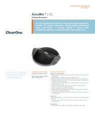
PASS-THROUGH MOUNTING ASSEMBLYThis assembly includes a threaded body with integrated mini-XLR and RJ45 connectors, andthe required washers and nuts for fastening in a suspended ceiling tile.<strong>Microphone</strong> <strong>Array</strong> EndIncludes 4-pin Mini-XLR ConnectorCable to Mixer EndIncludes Female RJ45 ConnectorTOOLS REQUIREDYou will need a drill and a 1-inch hole saw bit to install the mounting adapter, and an adjustablewrench to tighten the adapter fittings.DETERMINING THE PLACEMENTDetermine the placement of the <strong>Ceiling</strong> <strong>Microphone</strong> <strong>Array</strong> by the characteristics of the roomwhere it will be installed and the pickup pattern of the microphone array. The choice of eitherthe 12 or 24-inch microphone cable determines how close the microphone array is to the usersbelow and how wide the pickup pattern extends. Single and Dual <strong>Array</strong> pickup patterns andplacements are illustrated below:SINGLE MICROPHONE ARRAY PICK-UP PATTERNDUAL MICROPHONE ARRAY PICK-UP PATTERN120° from mic array(Best pick-up)180° from mic array(Good pick-up)120° from either mic array(Best pick-up)180° from either mic array(Good pick-up)3 Technical Support: 800.283.5936
INSTALLING THE MICROPHONE ARRAY1. Drop the ceiling tile where you have selected to install the microphone array.2. Run the 25-ft RJ45 cable from the mixer location into the space above the suspendedceiling and down through the opening of the removed tile to conceal the cable.3. Drill a 1-inch hole through each removed ceiling tile where the pass-through MountingAssembly will be placed.Drill 1-Inch Hole forPlacement of MountingAssembly4. Insert the Mounting Assembly through the hole with the RJ45 end above the ceiling tile,then tighten into place with the washers against both faces of the tile followed by thenuts. Be sure to place the washer and nut on the mini-XLR end as close to the end of thethreaded assembly as possible to allow the microphone array cable and grommet to fitsnugly against the ceiling tile.INSTALLATION MANUAL 4
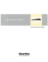
Above <strong>Ceiling</strong>Tile SurfaceBelow <strong>Ceiling</strong>Tile Surface5. Plug the RJ45 cable into the top end of Mounting Assembly, then lift the ceiling tile backinto place.6. Make sure the mini-XLR cable is fed through the grommet. Connect the mini-XLR connectorinto the receiving plug at the bottom of the Mounting Assembly, then slide the Grommet overthe cable and connector snugging it over the Mounting Assembly against the ceiling tile.RJ45 PlugMini-XLR Connector below<strong>Ceiling</strong> Tile SurfaceRJ45 Connector above<strong>Ceiling</strong> Tile SurfaceMini-XLR PlugGrommet5 Technical Support: 800.283.5936
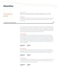
7. Attach the <strong>Microphone</strong> <strong>Array</strong> to the hanging end of the mini-XLR cable.8. Connect the RJ45 Male to Mixer adapter cable for your mixer: The Converge Pro requiresthe RJ45 to mini-Phoenix adapter cable. The RJ45 to XLR-M adapter is for the Interact Proand Interact AT mixers.9. Connect the CAT5e cable from the <strong>Ceiling</strong> <strong>Microphone</strong> <strong>Array</strong> to the adapter cable orderedto match the microphone inputs on the mixer.Mini-Phoenix Adapterfor Converge Pro andInteract Pro MixersXLR-M Adapter forthe Interact AT MixerCAT5e Cable Inputs»»Note: There are three connectors that plug into the mixer, one for each of the threemicrophones in the array.INSTALLATION MANUAL 6
Software Setup of the <strong>Ceiling</strong> <strong>Microphone</strong> <strong>Array</strong>The <strong>Ceiling</strong> <strong>Microphone</strong> <strong>Array</strong> can be used with the <strong>ClearOne</strong> Converge Pro, Interact Pro, andInteract AT audio conferencing mixers. Each <strong>Ceiling</strong> <strong>Microphone</strong> <strong>Array</strong> requires 3 microphoneinputs.Attention Installers: You must apply the software setup and filter settings in theaudio conferencing mixer to obtain the best performance from the <strong>ClearOne</strong> <strong>Ceiling</strong><strong>Microphone</strong> <strong>Array</strong>. Failure to apply these filter settings will result in degraded audioperformance.CONVERGE PRO MICROPHONE ARRAY SETUP1. With Converge Console connect to the Converge Pro.2. In Converge Console go to the channel view for the first microphone input.3. Verify PPWR (Phantom Power) is turned on. The <strong>Ceiling</strong> <strong>Microphone</strong> requires phantompower for operation.4. As a starting point set the Coarse Gain to 50 dB and the Fine Gain to 0 dB. Dependingon your application and the user to microphone distance, the gain settings may need tobe adjusted.5. Click on the NC button and Enable Noise Canceller. Set the Cancellation Depth to 6dB. This can be adjusted, if desired, based on your application.7 Technical Support: 800.283.5936
6. Click on the Filter Tab.7. Add 3 filtersFilter 1 is a PEQ filter with the center frequency at 100 Hz with a gain of 5 dB anda Q of 0.40Filter 2 is a PEQ filter with the center frequency at 4000 Hz with a gain of -2 dB anda Q of 0.27Filter 3 is a Low Pass filter set at 12000 Hz8. Other settings in the microphone channel can be set or adjusted based on your application.9. Repeat these steps for the other <strong>Ceiling</strong> <strong>Microphone</strong> <strong>Array</strong> inputs.INSTALLATION MANUAL 8
INTERACT PRO MICROPHONE ARRAY SETUP1. With the Interact software connect to the Interact Pro.2. In the Interact Software go to the Mic Settings screen3. Verify P Pwr (Phantom Power) is turned on. The <strong>Ceiling</strong> <strong>Microphone</strong> <strong>Array</strong> requires phantompower for operation.4. As a starting point set the Coarse Gain to 49 dB and the Fine Gain to 1 dB. Dependingon your application and the user to microphone distance, the gain settings may need tobe adjusted.5. Click on the Processing Tab.6. Enable the NC button and set the Cancellation Depth to 6dB.7. Click on the Filter button for the first microphone input.8. Add 3 filtersFilter 1 is a PEQ filter with the center frequency at 100 Hz with a gain of 5 dB anda Q of 0.40Filter 2 is a PEQ filter with the center frequency at 4000 Hz with a gain of -2 dB anda Q of 0.27Filter 3 is a Low Pass filter set at 12000 Hz9 Technical Support: 800.283.5936
9. Other settings in the <strong>Microphone</strong> Settings screen can be set or adjusted based on yourapplication.10. Repeat the filter setup for the other 2 <strong>Ceiling</strong> <strong>Microphone</strong> <strong>Array</strong> inputs.INSTALLATION MANUAL 10
INTERACT AT MICROPHONE ARRAY SETUP1. With the Interact software connect to the Interact AT.2. In the Interact Software go to the Mic Settings screen3. Verify P Pwr (Phantom Power) is turned on. The <strong>Ceiling</strong> <strong>Microphone</strong> <strong>Array</strong> requires phantompower for operation.4. As a starting point set the Coarse Gain to 49 dB and the Fine Gain to 1 dB. Dependingon your application and the user to microphone distance, the gain settings may need tobe adjusted.5. Click on the Processing Tab.6. Enable the NC button and set the Cancellation Depth to 6dB.7. Click on the Filter button for the first microphone input.8. Add 3 filtersFilter 1 is a PEQ filter with the center frequency at 100 Hz with a gain of 5 dB anda Q of 0.40Filter 2 is a PEQ filter with the center frequency at 4000 Hz with a gain of -2 dB anda Q of 0.27Filter 3 is a Low Pass filter set at 12000 Hz11 Technical Support: 800.283.5936
9. Other settings in the <strong>Microphone</strong> Settings screen can be set or adjusted based on yourapplication.10. Repeat the filter setup for the other 2 <strong>Ceiling</strong> <strong>Microphone</strong> <strong>Array</strong> inputs.INSTALLATION MANUAL 12
ComplianceCOMPLIANCE OVERVIEWROHS COMPLIANCEAll components and processes used to produce the <strong>Ceiling</strong> <strong>Microphone</strong> <strong>Array</strong> will comply withthe RoHS initiative.SUSTAINABILITYThe <strong>Ceiling</strong> <strong>Microphone</strong> <strong>Array</strong> is compliant with the WEEE recycling initiative. It is made fromeasily recyclable materials such as aluminum and steel.ELECTRICAL SAFETY ADVISORYThis equipment uses DC power supplied from an external source which can be subjected toelectrical surges, typically lightning transients which are very destructive to customer terminalequipment. The warranty for this equipment does not cover damage caused by electricalsurge or lightning transients. To reduce the risk of this equipment becoming damaged it issuggested that the customer consider installing a surge arrestor.13 Technical Support: 800.283.5936
Service and SupportIf you need assistance setting up or operating your product, please contact us. We welcomeyour comments so we can continue to improve our products and better meet your needs.Technical SupportTelephone: 1.800.283.5936E-mail: tech.support@<strong>ClearOne</strong>.comWeb site: www.<strong>ClearOne</strong>.com, www.NetStreams.comSalesTelephone: 1.800.707.6994E-mail: sales@<strong>ClearOne</strong>.comTechsalesTelephone: 1.800.705.2103E-mail: techsales@<strong>ClearOne</strong>.comProduct ReturnsAll product returns require a Return Material Authorization (RMA) number. Contact <strong>ClearOne</strong>Technical Support before returning your product. Make sure you return all the items andpacking materials that originally shipped with your product.CLEARONE LOCATIONSHEADQUARTERS:Salt Lake City, UT USA5225 Wiley Post WaySuite 500Salt Lake City, UT 84116Tel: 801.975.7200Toll Free: 800.945.7730Fax: 801.977.0087e-mail: sales@clearone.comEMEATel: 44 (0) 1189.036.053e-mail: global@clearone.comAPACTel: 801.303.3388e-mail: global@clearone.comLATAMTel: 801.974.3621e-mail: global@clearone.comTechSalesTel: 800.705.2103e-mail: techsales@clearone.comTechnical SupportTel: 800.283.5936e-mail: tech.support@clearone.comINSTALLATION MANUAL 14
<strong>Ceiling</strong> <strong>Microphone</strong> <strong>Array</strong> <strong>Installation</strong> <strong>Manual</strong><strong>ClearOne</strong> Document800-001-013 - Jan. 9, 2012 (Rev. 1.3)© 2012 <strong>ClearOne</strong> All rights reserved. No part of this documentmay be reproduced in any form or by any means without writtenpermission from <strong>ClearOne</strong>. <strong>ClearOne</strong> reserves specific privileges.Information in this document is subject to change without notice.
<strong>ClearOne</strong>5225 Wiley Post WaySuite 500Salt Lake City, UT 84116Telephone 1.800.283.59361.801.974.3760FAX 1.801.974.3669E-mailtech.support@clearone.comOn the Web www.clearone.com