NFPA Cylinders Type DNA - Allied Automation, Inc.
NFPA Cylinders Type DNA - Allied Automation, Inc.
NFPA Cylinders Type DNA - Allied Automation, Inc.

You also want an ePaper? Increase the reach of your titles
YUMPU automatically turns print PDFs into web optimized ePapers that Google loves.
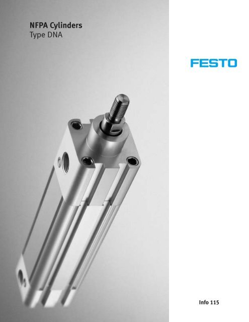
<strong>NFPA</strong> <strong>Cylinders</strong><strong>Type</strong> <strong>DNA</strong>Info 115
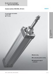
<strong>NFPA</strong> <strong>Cylinders</strong>, <strong>Type</strong> <strong>DNA</strong>ContentsSquare Head Industrial <strong>Cylinders</strong> Bore Sizes: 1½ ... 5 Stroke Lengths: ½ ... 80A Modern Design<strong>Type</strong> <strong>DNA</strong> <strong>Cylinders</strong>, with its modern designand popular range of diameters, offermany benefits for higher productivity.Key Features ........................................... 4-5Overview ................................................ 6-7Ordering Example ................................... 8-9Cylinder Variations ............................. 10-11Ordering Data .................................... 12-13Technical Data ................................... 14-19Dimensions ....................................... 20-21Accessories ....................................... 22-38The Solution for Your Pneumatic Actuator RequirementsThe <strong>DNA</strong> ActuatorLong service life is a required featurein today’s and tomorrow’s industrialenvironment. A cylinder made fordemanding applications does notneed to be bulky and heavy. Currenttechnology and Festo’s renownedexperience in the field of pneumaticactuator design has resulted inthe development of a versatile,economical and tough cylinder forapplications in many industries.Festo took the challenge; wedesigned and built a cylinder basedon these requirements. The result isthe <strong>DNA</strong> cylinder which exceeds ourown benchmark specifications, and iscompatible with the <strong>NFPA</strong> Standard.<strong>DNA</strong> cylinders are rugged, state-ofthe-artactuators for OEMs and endusers. Install <strong>DNA</strong> cylinders in yourmachine or process operation anddowntime is a thing of the past! Extruded aluminum barrel for lightweight. Integrated sensor groovesachieves a space-saving design. Popular and universal proximitysensors, also used for a widevariety of Festo cylinder types –reduces inventory and spare parts. Roller burnished piston rods andthreads for superior service life. Made to order – fast delivery Built-in adjustable cushioningscrews (optional) and portconnections (same face) onboth end caps – more convenientaccessibility. Wide variety of mountings arefactory assembled or suppliedseparately – no need to stock allcylinder variations. Innovative mounting attachmentsystem simplifies configuration ofdesired mounting styles – savesdisassembly time wheneverchanges are made.<strong>NFPA</strong> Standards<strong>DNA</strong> series square head cylindersmeet the mounting, rod, bore andthread dimension specifications asdescribed in the following <strong>NFPA</strong>documents:ANSI/B93.8-1968[R1992]/<strong>NFPA</strong> T3.6.4-1967 Bore and rod size combinationsand rod end configurations forcataloged square head industrialfluid power cylinders.ANSI/[<strong>NFPA</strong>] T3.6.7R2-1996 Mounting dimensions, fluid powersystems and products, square headindustrial cylinder.ANSI/B93.29M-1986/<strong>NFPA</strong> T3.6.8M R1-1984 Accessory dimensions for catalogedsquare head industrial types, fluidpower systems, cylinders.<strong>NFPA</strong> T3.6.17-1971[1990] Port nominal pipe sizes for mergedinch and metric series catalogedsquare head industrial pneumaticfluid power cylinders.06/2006 – Subject to change – <strong>NFPA</strong> <strong>Cylinders</strong> 3
<strong>NFPA</strong> <strong>Cylinders</strong>, <strong>Type</strong> <strong>DNA</strong>Double-actingKey Features<strong>DNA</strong>-...-P-A<strong>DNA</strong>-...-PPV-ASquare Head Industrial <strong>Cylinders</strong> Bore Sizes: 1½ ... 5 Stroke Lengths: ½ ... 80Two Basic Models Double-acting standard cylinderfor non-contact end-positionsensing (A) with flexible endposition cushioning (P)Example: <strong>DNA</strong>-...-P-A Double-acting standard cylinderfor non-contact end-positionsensing (A) with adjustableend-position cushioning (PPV)Example: <strong>DNA</strong>-...-PPV-A Standard cylinders are <strong>NFPA</strong>interchangeable. <strong>DNA</strong><strong>NFPA</strong>cylinderscanbeordered as a product moduleassembledwithselectedaccessories (see pages 8-9). <strong>DNA</strong><strong>NFPA</strong>cylinderscanalsobeorderedasstandardcylinderswithout variants, just specifystroke length (see pages 12-13). Of course, A broad range ofaccessories are available.4<strong>NFPA</strong> <strong>Cylinders</strong> – Subject to change – 06/2006
<strong>NFPA</strong> <strong>Cylinders</strong>, <strong>Type</strong> <strong>DNA</strong>Double-actingCylinder Variations (See pages 10-11 for details)S1: Reinforced piston rodK3: Pistonrodwithfemalethread(<strong>NFPA</strong> style SF; short female)S2: Double-ended piston rodK5: Pistonrodwithspecialthread(<strong>NFPA</strong> style IM; intermediate male)K0: Piston rod without thread(<strong>NFPA</strong> style PL; plain)K8: Extended piston rodK2: Pistonrodwithextendedmale threadS6: Heat-resistant seals, max. 302° FNote: Standard cylinder comes with small male thread (<strong>NFPA</strong> style SM; short male)Key Features Allen screws with internal threadsfor mounting <strong>NFPA</strong> accessories 1 No protruding sensors-lowprofilesensors mount flush in grooves21 Internal mounting SME/SMT-8cylinder sensor (no brackets orhardware required) Slot covers protect sensor cablesand form smooth surface Additional cushioning rings onthe piston and adjustable aircushioning 2 is available forabsorbing the residual energy fromhigh speeds and machine cycles06/2006 – Subject to change – <strong>NFPA</strong> <strong>Cylinders</strong> 5
<strong>NFPA</strong> <strong>Cylinders</strong>, <strong>Type</strong> <strong>DNA</strong>Double-actingOverviewMounting Attachments and Accessories1768 *53aIaE* View rotated 180°4aD3aJ4aGaH9aCaAaB7aF626<strong>NFPA</strong> <strong>Cylinders</strong> – Subject to change – 06/2006
<strong>NFPA</strong> <strong>Cylinders</strong>, <strong>Type</strong> <strong>DNA</strong>Double-actingOverviewMounting Attachments and Accessories1 Head Rectangular Flange,MF1-...2 Cap Rectangular Flange,MF2-...3 Head Trunnion Mounting,MT1-...4 Cap Trunnion Mounting,MT2-...5 Mid Trunnion Mounting,MT4-... (patent pending)6 Side End Angle Mount,MS1-...7 Side Lug Mount,MS2-...8 Side Tap Mount,MS4-...9 Cap Fixed Clevis,MP1-...aJ Cap Detachable Clevis,MP2-...aA Cap Detachable Eye,MP4-...aB Clevis Bracket,LNA-...aC Eye Bracket,LNB-...aD Female Clevis,SSA-...aE Female Eye,SSB-...aF Pivot Pin,BO-...aG Integrable Cylinder Sensor,SME/SMT-8-...aH Slot Cover for Sensor Slot(19.5 long) ABP-5-SaI Flow Control,GRLA-...Both Ends Tie RodsExtended Mounting, MX1-...Cap Tie Rods ExtendedMounting, MX2-...Head Tie Rods ExtendedMounting, MX3-...06/2006 – Subject to change – <strong>NFPA</strong> <strong>Cylinders</strong> 7
<strong>NFPA</strong> <strong>Cylinders</strong>, <strong>Type</strong> <strong>DNA</strong>Double-actingOrdering ExampleThe procedure for constructingthe correct order code consistsof 2 steps.Step 1Determining if a permissible cylindervariation combination is available:The desired cylinder variations in thisexampleareS2,K3,K8,S6,andMF1.Arrange these variations in sequenceas they appear from top to bottom inthe “Desired Cylinder Variation”column from the table on the right.Once you have determined that allof the desired cylinder variations areavailable in combination, choosethe mounting style. Furthermore,make sure the required bore andstroke are also possible, thenproceed to step 2.Step 2Create an order code:Usetheexamplebelowandthe“Order Code Table” as your guide.When you have chosen your desiredconfiguration, transfer the code tothe bottom of page 9. This is yourorder code.Part No. 193384 <strong>DNA</strong> – 2 – 10 – PPV-A – S2 – K3 – 6K8 – S6 – MF1<strong>Type</strong><strong>DNA</strong>Standard cylinderBore Size [<strong>Inc</strong>h]2 2Stroke Length [<strong>Inc</strong>h]10 10End Position CushioningP-APPV-APosition cushioning with non-contact positionsensing magnetAdjustable end-position cushioning withnon-contact position sensing magnetVariationsS1 Reinforced pistion rodS2 Double-ended piston rodK0 Piston rod without thread...K2 Pistonrodwithextendedmalethread(example, 1.5 = 1.5K2)...K3 Pistonrodwithfemalethread...K5 Pistonrodwithspecialthread (example,1=1K5)...K8 Extended piston rod (example, 6 = 6K8)S6 Heat-resistant sealsMounting StyleMF1MF2MT1MT2MT4MS1MS2MS4MP1MP2MP4MX1MX2MX3Head rectangular flangeCap rectangular flangeHead trunnion mountCap trunnion mountMid trunnion mount (patent pending)Side end angle mountSide lug mountSide tap mountCap fixed clevisCap detachable clevisCap detachable eyeBoth ends tie rods extended mountingCap tie rods extended mountingHead tie rods extended mounting8<strong>NFPA</strong> <strong>Cylinders</strong> – Subject to change – 06/2006
<strong>NFPA</strong> <strong>Cylinders</strong>, <strong>Type</strong> <strong>DNA</strong>Double-actingPermissible Cylinder VariationsStep 1DesiredCylinderVariationBore ∅[inch]Stroke*[inch]P PPV**AMX1MX2MX3MP1MP2MP4Cylinder Variation CombinationsS6 K8 K5 K3 K2 K0 S2 S1MS1MS2MS4MT1MT2MT4MF1MF2S1 1½ to 5 0.5 to 80 † †S2 1½ to 5 0.5 to 80 – – – – – –K0 1½ to 5 0.5 to 80 – – –K2 1½ to 5 0.5 to 80 –K3 1½ to 5 0.5 to 80 –K5 1½ to 5 0.5 to 80K8 1½ to 5 0.5 to 80S6 1½ to 5 0.5 to 80* The stroke for 3¼, 4 and 5 cylinders starts at 0.7** Not for front cap 1½ with rod diameter of 1– Not availableCombination is possible† Not available for 1½Order Code TableStep 2Function Description/Characteristics Code EnterPart No. 193383 193384 193385 193386 193387 193388<strong>Type</strong>/Function Double-acting cylinder <strong>DNA</strong> <strong>DNA</strong>Bore Size 1½ 2 2½ 3¼ 4 5 -...Stroke Length 0.5 ... 80 0.75 ... 80 -...<strong>Type</strong> of Cushioning Flexible cushioning rings in the end-positions with end-position sensing -P-AAdjustable end-position cushioning with end-position sensing-PPV-A<strong>Type</strong> of Piston Rod Reinforced piston rod -S1Double-ended piston rod -S2Piston rod without thread -K0Extended male piston rod thread0.04 ... 1.78 0.04 ... 2.75 -...K2Standard Thread Pistonrodwithsmallmalethread(<strong>NFPA</strong>StyleSM)Bore size 1½ 1½-S1 2 2-S1 2½ 2½-S1 3¼ 3¼-S1 4 4-S1 5 5-S1Rod size (nominal) 5/8 1 5/8 1 5/8 1 1 1¼* 1 1¼* 1 1¼*StandardThread [UNF-2A] 7 16 -20 ¾-16 7 16 -20 ¾-16 7 16 -20 ¾-16 ¾-16 1-14 ¾-16 1-14 ¾-16 1-14Female Thread Pistonrodwithfemalethread(<strong>NFPA</strong>StyleSF) -...K3Bore size 1½ 1½-S1 2 2-S1 2½ 2½-S1 3¼ 3¼-S1 4 4-S1 5 5-S1Rod size (nominal) 5/8 1 5/8 1 5/8 1 1 1¼* 1 1¼* 1 1¼*Thread [UNF-2B] 7 16 -20 ¾-16 7 16 -20 ¾-16 7 16 -20 ¾-16 ¾-16 1-14 ¾-16 1-14 ¾-16 1-14Special Thread Pistonrodwithintermediatemalethread(<strong>NFPA</strong>StyleIM) -...K5Bore size 1½ 1½-S1 2 2-S1 2½ 2½-S1 3¼ 3¼-S1 4 4-S1 5 5-S1Rod size (nominal) 5/8 1 5/8 1 5/8 1 1 1¼* 1 1¼* 1 1¼*Thread [UNF-2A] ½-20 7 8 -14 ½-20 7 8 -14 ½-20 7 8 -14 7 8 -14 1¼-12 7 8 -14 1¼-12 7 8 -14 1¼-12Extended Piston Rod 0.04 ... 20 -...K8Temperature Resistance Heat-resistant seals up to 302 °F (Viton) -S6Mounting Style Seepage8fordescriptionsandcodes -...Weights SeePage15aMandndato ory DataaOptiononal Data* Deviates from <strong>NFPA</strong> dimension [<strong>NFPA</strong> = 1.375]Transfer Order CodePart No. = <strong>DNA</strong> – – – – – – – –06/2006 – Subject to change – <strong>NFPA</strong> <strong>Cylinders</strong> 9
<strong>NFPA</strong> <strong>Cylinders</strong>, <strong>Type</strong> <strong>DNA</strong>Double-actingCylinder Variations - The <strong>DNA</strong> cylinder modular system permits the following variants; these can be combined with each other with some exceptions ( SeePage9).S1: Reinforced Piston RodLarger diameter piston rod, see page 21.S2: Double Ended Piston RodOrder Code: ...-S2-...Note: The thread design on both pistonrod ends are identical.K0: Piston Rod Without Thread(WF)K2: PistonRodwithExtendedMaleThreadA1 A Bore ∅[inch]AA1max.Standard Thread[SM]1½ 0.750 7 16 -20 UNF-2B1½-S1 1.125 1.375 ¾-16 UNF-2B2 0.750 7 16 -20 UNF-2B2-S1 1.125 ¾-16 UNF-2B2½ 0.750 7 16 -20 UNF-2B2½-S1 1.125 ¾-16 UNF-2BOrder Code: ...-xxK2-... 3¼ 1.125 2.250 ¾-16 UNF-2BExample: xx = 2¼ inches ...-2.25K2-... 3¼-S1 1.625 1-14 UNF-2B4 1.125 ¾-16 UNF-2B4-S1 1.625 1-14 UNF-2B5 1.125 ¾-16 UNF-2B5-S1 1.625 1-14 UNF-2BSMSKKK3: PistonRodwithFemaleThreadWFTBore ∅[inch]T WF Standard Thread[KK]1½ 0.79 1.000 7 16 -20 UNF-2B1½-S1 1.18 1.375 ¾-16 UNF-2B2 0.79 1.000 7 16 -20 UNF-2BK2-S11.18 1.375 ¾-16 UNF-2B2½ 0.79 1.000 7 16 -20 UNF-2B2½-S1 1.18 1.375 ¾-16 UNF-2B3¼ 1.18 1.375 ¾-16 UNF-2B3¼-S1 1.67 1.675 1-14 UNF-2BOrder Code: ...-K3-... 4 1.18 1.375 ¾-16 UNF-2B4-S1 1.67 1.675 1-14 UNF-2B5 1.18 1.375 ¾-16 UNF-2B5-S1 1.67 1.675 1-14 UNF-2B10<strong>NFPA</strong> <strong>Cylinders</strong> – Subject to change – 06/2006
<strong>NFPA</strong> <strong>Cylinders</strong>, <strong>Type</strong> <strong>DNA</strong>Double-actingCylinder Variations - The <strong>DNA</strong> cylinder modular system permits the following variants; these can be combined with each other with some exceptions ( SeePage9).K5: Special Thread On Piston RodIMOrder Code: ...-...K5-...Example: ... = ½-20-UNF-2A ...-K5-...Bore∅[inch]Piston rod ∅[inch]Nominal (Actual)Standard thread[SM]Special thread1½ 5/8 (0.630) 7 16 -20 UNF-2A ½-20-UNF-2A1½-S1 1 (0.984) ¾-16 UNF-2A 7 8 -14 UNF-2A2 5/8 (0.630) 7 16 -20 UNF-2A ½-20-UNF-2A2-S1 1 (0.984) ¾-16 UNF-2A 7 8 -14 UNF-2A2½ 5/8 (0.630) 7 16 -20 UNF-2A ½-20-UNF-2A2½-S1 1 (0.984) ¾-16 UNF-2A 7 8 -14 UNF-2A3¼ 1 (0.984) ¾-16 UNF-2A 7 8 -14 UNF-2A3¼-S1 1¼ (1.260*) 1-14 UNF-2A 1¼-20-UNF-2A4 1 (0.984) ¾-16 UNF-2A 7 8 -14 UNF-2A4-S1 1¼ (1.260*) 1-14 UNF-2A 1¼-20-UNF-2A5 1 (0.984) ¾-16 UNF-2A 7 8 -14 UNF-2A5-S1 1¼ (1.260*) 1-14 UNF-2A 1¼-20-UNF-2A[IM]* Deviates from <strong>NFPA</strong> dimension [<strong>NFPA</strong> = 1.375]K8: Extended Piston RodOrder Code: ...-xxK8-...Example: xx = 6 inch ...-6K8-...Note:If variant K8 is required in combinationwith S2, the piston rod extension willoccur only on one side.SM(Y+A2)+(WF+A2)+A2(ZJ+A2)++ = plus stroke lengthBoreA2 WF Y ZJ Standard Thread∅[inch] max. max.[SM]1½ 0.04 20 1.000 1.878 4.625 7 16 -20 UNF-2A1½-S1 0.04 20 1.375 2.252 5.000 ¾-16 UNF-2A2 0.04 20 1.000 1.882 4.625 7 16 -20 UNF-2A2-S1 0.04 20 1.375 2.252 5.000 ¾-16 UNF-2A2½ 0.04 20 1.000 1.953 4.750 7 16 -20 UNF-2A2½-S1 0.04 20 1.375 2.307 5.125 ¾-16 UNF-2A3¼ 0.04 20 1.375 2.441 5.625 ¾-16 UNF-2A3¼-S1 0.04 20 1.625 2.697 5.875 1-14 UNF-2A4 0.04 20 1.375 2.441 5.625 ¾-16 UNF-2A4-S1 0.04 20 1.625 2.697 5.875 1-14 UNF-2A5 0.04 20 1.375 2.441 5.875 ¾-16 UNF-2A5-S1 0.04 20 1.625 2.693 6.125 1-14 UNF-2AS6: Heat-Resistant Seals [302 °F]Order Code: ...-S6-...Material: Seals are made of FKM (Viton)06/2006 – Subject to change – <strong>NFPA</strong> <strong>Cylinders</strong> 11
<strong>NFPA</strong> <strong>Cylinders</strong>, <strong>Type</strong> <strong>DNA</strong>Double-actingOrdering DataStandard <strong>Cylinders</strong>Stroke[inch]Bore Size 1½Part No. <strong>Type</strong>Bore Size 2Part No. <strong>Type</strong>Bore Size 2½Part No. <strong>Type</strong>X-stroke length ... 193383 <strong>DNA</strong>-1½-...-P-A 193384 <strong>DNA</strong>-2-...-P-A 193385 <strong>DNA</strong>-2½-...-P-AX-stroke length ... 193383 <strong>DNA</strong>-1½-...-PPV-A 193384 <strong>DNA</strong>-2-...-PPV-A 193385 <strong>DNA</strong>-2½-...-PPV-ATechnical Data SeePage14Accessories<strong>Type</strong> Bore Size 1½ Bore Size 2 Bore Size 2½Head Rectangular Flange MF1 Page 22Cap Rectangular Flange MF2 Page 22Cap Trunnion-Mounting MT1 Page 23Head Trunnion-Mounting MT2 Page 23Mid Trunnion-Mounting MT4* Page 23Side End Angle Mount MS1 Page 24Side Lug Mount MS2 Page 25Side Tap Mount MS4 Page 26Cap Fixed Clevis MP1 Page 27Cap Detachable Clevis MP2 Page 28Cap Detachable Eye MP4 Page 29Both Ends Tie Rods Extended Mounting MX1 Page 30Cap Tie Rods Extended Mounting MX2 Page 30Head Tie Rods Extended Mounting MX3 Page 30Clevis Bracket LNA Page 31Eye Bracket LNB Page 32Female Clevis SSA Page 33Female Eye SSB Page 34Pivot Pin BO Page 35Hex Jam Nut B Page 35SlotCover(forsensorgroove) ABP-5-S Page 36Flow Control GRLA Page 36Sensor SME-8 Page 37Sensor SMT-8 Page 38* Patent Pending12<strong>NFPA</strong> <strong>Cylinders</strong> – Subject to change – 06/2006
<strong>NFPA</strong> <strong>Cylinders</strong>, <strong>Type</strong> <strong>DNA</strong>Double-actingOrdering DataStandard <strong>Cylinders</strong>Stroke[inch]Bore Size 3¼Part No. <strong>Type</strong>Bore Size 4Part No. <strong>Type</strong>Bore Size 5Part No. <strong>Type</strong>X-stroke length ... 193386 <strong>DNA</strong>-3¼-...-P-A 193387 <strong>DNA</strong>-4-...-P-A 193388 <strong>DNA</strong>-5-...-P-AX-stroke length ... 193386 <strong>DNA</strong>-3¼-...-PPV-A 193387 <strong>DNA</strong>-4-...-PPV-A 193388 <strong>DNA</strong>-5-...-PPV-ATechnical Data SeePage14Accessories<strong>Type</strong> Bore Size 3¼ Bore Size 4 Bore Size 5Head Rectangular Flange MF1 Page 22Cap Rectangular Flange MF2 Page 22Cap Trunnion-Mounting MT1 Page 23Head Trunnion-Mounting MT2 Page 23Mid Trunnion-Mounting MT4 Page 23Side End Angle Mount MS1 Page 24Side Lug Mount MS2 Page 25Side Tap Mount MS4 Page 26Cap Fixed Clevis MP1 Page 27Cap Detachable Clevis MP2 Page 28Cap Detachable Eye MP4 Page 29Both Ends Tie Rods Extended Mounting MX1 Page 30Cap Tie Rods Extended Mounting MX2 Page 30Head Tie Rods Extended Mounting MX3 Page 30Clevis Bracket LNA Page 31Eye Bracket LNB Page 32Female Clevis SSA Page 33Female Eye SSB Page 34Pivot Pin BO Page 35Hex Jam Nut B Page 35SlotCover(forsensorgroove) ABP-5-S Page 36Flow Control GRLA Page 36Sensor SME-8 Page 37Sensor SMT-8 Page 3806/2006 – Subject to change – <strong>NFPA</strong> <strong>Cylinders</strong> 13
<strong>NFPA</strong> <strong>Cylinders</strong>, <strong>Type</strong> <strong>DNA</strong>Double-actingTechnical DataSquare Head Industrial <strong>Cylinders</strong><strong>DNA</strong>-...-P-ATwo Basic Models Double-acting standard cylinderfor non-contact end-positionsensing (A) with flexible endposition cushioning (P)Example: <strong>DNA</strong>-...-P-A Bore Sizes: 1½ ... 5 Stroke Lengths: ½ ... 80<strong>DNA</strong>-...-PPV-A Double-acting standard cylinderfor non-contact end-positionsensing (A) with adjustableend-position cushioning (PPV)Example: <strong>DNA</strong>-...-PPV-ATechnical DataMediumDesignOperating pressureTemperature rangeVariant S6MaterialBearing and end capsAnodized AluminumCylinder barrelAnodized AluminumPiston rod Stainless steel 316SealsPolyurethaneVariant S6 FKM (Viton)Dried compressed air [lubicated or unlubicated]Double-acting pneumatic cylinder with piston rod9 to 180 psi–4 to 176° F–4 to 302° FBore Size[inch]Extended Forceat 90psi*[lbf]Return Forceat 90psi*[lbf]Head Cushioning LengthAir Cushioning[inch]Cap Cushioning LengthAir Cushioning[inch]Port Connection1½ 170 142 0.8 0.6 y –18NPT1½-S1 170 103 – 0.6 y –18NPT2 265 238 0.7 0.6 y –18NPT2-S1 265 200 1.0 0.6 y –18NPT2½ 420 394 0.7 0.6 y –18NPT2½-S1 420 355 1.0 0.6 y –18NPT3¼ 678 612 1.2 0.8 ½–14NPT3¼-S1 678 570 1.0 0.8 ½–14NPT4 1059 994 1.2 0.8 ½–14NPT4-S1 1059 952 1.0 0.8 ½–14NPT5 1655 1591 1.2 0.7 ½–14NPT5-S1 1655 1548 1.0 0.7 ½–14NPTThread* Theoretical valuesNote: Values calculated with 5/8 and 1 rod sizes.14<strong>NFPA</strong> <strong>Cylinders</strong> – Subject to change – 06/2006
<strong>NFPA</strong> <strong>Cylinders</strong>, <strong>Type</strong> <strong>DNA</strong>Double-actingTechnical DataSquare Head Industrial <strong>Cylinders</strong><strong>Type</strong>WeightsBasic Weight[lbs]<strong>DNA</strong>-1½-... 1.575 0.218<strong>DNA</strong>-1½-...-S1 2.067 0.347<strong>DNA</strong>-2-... 2.392 0.300<strong>DNA</strong>-2-...-S1 2.841 0.429<strong>DNA</strong>-2½-... 3.330 0.373<strong>DNA</strong>-2½-...-S1 3.816 0.502<strong>DNA</strong>-3¼-... 6.429 0.608<strong>DNA</strong>-3¼-...-S1 7.179 0.748<strong>DNA</strong>-4-... 8.870 0.716<strong>DNA</strong>-4-...-S1 9.602 0.858<strong>DNA</strong>-5-... 12.821 0.949<strong>DNA</strong>-5-...-S1 13.575 1.089Weight per 1 inch Stroke[lbs]06/2006 – Subject to change – <strong>NFPA</strong> <strong>Cylinders</strong> 15
<strong>NFPA</strong> <strong>Cylinders</strong>, <strong>Type</strong> <strong>DNA</strong>Double-actingTechnical DataStandard CylinderCylinder BoreSize:1½, 2, 2½Rod Size: 5 8 (Standard)Lateral force F Q in relation to stroke lengthLateral force FQ [lbf]121117112108103999490858176726763595450454136322722181495031420.04 0.4 4 40Stroke length [inch]1 S62 Standard3 S6-S24 S216<strong>NFPA</strong> <strong>Cylinders</strong> – Subject to change – 06/2006
<strong>NFPA</strong> <strong>Cylinders</strong>, <strong>Type</strong> <strong>DNA</strong>Double-actingTechnical DataStandard CylinderCylinder Bore Size: 1½, 2, 2½Rod Size: 1 (Reinforced)Lateral force F Q in relation to stroke lengthLateral force FQ [lbf]304293281270259247236225214202191180169157146135124112101907967564534231104320.04 10.4 4 40Stroke length [inch]1 S1-S62 S13 S1-S6-S24 S1-S206/2006 – Subject to change – <strong>NFPA</strong> <strong>Cylinders</strong> 17
<strong>NFPA</strong> <strong>Cylinders</strong>, <strong>Type</strong> <strong>DNA</strong>Double-actingTechnical DataStandard CylinderCylinder Bore Size: 3¼, 4, 5Rod Size: 1 (Standard)Lateral force F Q in relation to stroke lengthLateral force FQ [lbf]2702592472362252142021911801691571461351241121019079675645342311043210.04 0.4 4 40Stroke length [inch]1 S62 Standard3 S6-S24 S218<strong>NFPA</strong> <strong>Cylinders</strong> – Subject to change – 06/2006
<strong>NFPA</strong> <strong>Cylinders</strong>, <strong>Type</strong> <strong>DNA</strong>Double-actingTechnical DataStandard CylinderCylinder Bore Size: 3¼, 4, 5Rod size: 1¼ (Reinforced)Lateral force F Q in relation to stroke lengthLateral force FQ [lbf]47245042740538236033731529227024722520218015713511290674523043210.04 0.4 4 40Stroke length [inch]1 S1-S62 S13 S1-S6-S24 S1-S206/2006 – Subject to change – <strong>NFPA</strong> <strong>Cylinders</strong> 19
<strong>NFPA</strong> <strong>Cylinders</strong>, <strong>Type</strong> <strong>DNA</strong>Double-actingDimensionsStandard <strong>Cylinders</strong><strong>DNA</strong>-...-P-A<strong>DNA</strong>-...-PPV-AD7Internalthread ofcap screwWS3AWFVDYL6L7ZJ+P+J3A EA RBMMSMJ7A J5J4J6ß WS2L5L10EEL9Variant S2ZJS2+L15+++ = plus stroke length++ = plus 2 x stroke length20<strong>NFPA</strong> <strong>Cylinders</strong> – Subject to change – 06/2006
<strong>NFPA</strong> <strong>Cylinders</strong>, <strong>Type</strong> <strong>DNA</strong>Double-actingDimensionsStandard <strong>Cylinders</strong><strong>Type</strong> A ∅BD7 E EE J3 J4 J5 J6-0.01-0.03<strong>DNA</strong> – 1½ 0.750 1.125 ¼-28 UNF 2.00 y-18 NPT 0.08 0.35 1.99 –<strong>DNA</strong> – 1½-S1 1.125 1.500 ¼-28 UNF 2.00 y-18 NPT 0.08 0.35 1.99 –<strong>DNA</strong> – 2 0.750 1.125 5 16 -24 UNF 2.50 y-18 NPT 0.12 0.48 2.47 0.12<strong>DNA</strong> – 2-S1 1.125 1.500 5 16 -24 UNF 2.50 y-18 NPT 0.12 0.48 2.47 –<strong>DNA</strong> – 2½ 0.750 1.125 5 16 -24 UNF 3.00 y-18 NPT 0.10 0.48 2.96 0.20<strong>DNA</strong> – 2½-S1 1.125 1.500 5 16 -24 UNF 3.00 y-18 NPT 0.10 0.48 2.96 –<strong>DNA</strong> – 3¼ 1.125 1.500 y-24 UNF 3.75 ½-14 NPT – 0.62 3.68 –<strong>DNA</strong> – 3¼-S1 1.625 2.000 y-24 UNF 3.75 ½-14 NPT – 0.62 3.68 –<strong>DNA</strong> – 4 1.125 1.500 y-24 UNF 4.50 ½-14 NPT 1.16 0.62 4.43 0.16<strong>DNA</strong> – 4-S1 1.625 2.000 y-24 UNF 4.50 ½-14 NPT 1.16 0.62 4.43 –<strong>DNA</strong> – 5 1.125 1.500 ½-20 UNF 5.50 ½-14 NPT – 0.79 5.35 0.16<strong>DNA</strong> – 5-S1 1.625 2.000 ½-20 UNF 5.50 ½-14 NPT – 0.79 5.35 –<strong>Type</strong> J7 L5 L6 L7 L9 L10 L15 MMPRNominal (Actual)<strong>DNA</strong> – 1½ 0.39 1.70 0.63 0.37 1.20 0.35 6.14 5/8 (0.630) 2.313 1.429<strong>DNA</strong> – 1½-S1 – 1.70 0.63 – 1.20 0.35 6.88 1 (0.984) 2.313 1.429<strong>DNA</strong> – 2 0.39 1.66 0.63 0.38 1.16 0.21 6.14 5/8 (0.630) 2.313 1.839<strong>DNA</strong> – 2-S1 0.60 1.66 0.63 0.27 1.16 0.21 6.88 1 (0.984) 2.313 1.839<strong>DNA</strong> – 2½ 0.39 1.66 0.63 0.29 1.16 0.34 6.28 5/8 (0.630) 2.375 2.193<strong>DNA</strong> – 2½-S1 0.60 1.66 0.63 0.29 1.16 0.34 6.99 1 (0.984) 2.375 2.193<strong>DNA</strong> – 3¼ 0.62 1.88 0.63 0.37 1.38 0.37 7.51 1 (0.984) 2.625 2.758<strong>DNA</strong> – 3¼S1 0.79 1.88 0.63 0.37 1.38 0.37 8.02 1¼ (1.260*) 2.625 2.758<strong>DNA</strong> – 4 0.62 1.86 0.63 0.23 1.36 0.23 7.51 1 (0.984) 2.625 3.323<strong>DNA</strong> – 4-S1 0.79 1.86 0.63 0.23 1.36 0.23 8.02 1¼ (1.260*) 2.625 3.323<strong>DNA</strong> – 5 0.62 1.76 1.00 0.28 1.26 0.29 7.76 1 (0.984) 2.875 4.101<strong>DNA</strong> – 5-S1 0.79 1.76 1.00 0.28 1.26 0.29 8.27 1¼ (1.260*) 2.875 4.101<strong>Type</strong> SM WS2 WS3 VD WF Y ZJ ZJS2<strong>DNA</strong> – 1½ 7 16 20 UNF-2A WF ½ HEX ¼ 0.625 1.000 1.878 4.625 5.125<strong>DNA</strong> – 1½-S1 ¾-16 UNF-2A WF 7 8 HEX ¼ 0.875 1.375 2.252 5.000 5.500<strong>DNA</strong> – 2 7 16 20 UNF-2A WF ½ HEX 5 16 0.625 1.000 1.882 4.625 5.125<strong>DNA</strong> – 2-S1 ¾-16 UNF-2A WF 7 8 HEX 5 16 0.875 1.375 2.252 5.000 5.500<strong>DNA</strong> – 2½ 7 16 20 UNF-2A WF ½ HEX 5 16 0.625 1.000 1.953 4.750 5.250<strong>DNA</strong> – 2½-S1 ¾-16 UNF-2A WF 7 8 HEX 5 16 0.875 1.375 2.307 5.125 5.625<strong>DNA</strong> – 3¼ ¾-16 UNF-2A WF 7 8 HEX ¼ 0.875 1.375 2.441 5.625 6.125<strong>DNA</strong> – 3¼-S1 1-14 UNF-2A WF 1x HEX ¼ 1.000 1.625 2.697 5.875 6.375<strong>DNA</strong> – 4 ¾-16 UNF-2A WF 7 8 HEX ¼ 0.875 1.375 2.441 5.625 6.125<strong>DNA</strong> – 4-S1 1-14 UNF-2A WF 1x HEX ¼ 1.000 1.625 2.697 5.875 6.375<strong>DNA</strong> – 5 ¾-16 UNF-2A WF 7 8 – 0.875 1.375 2.441 5.875 6.375<strong>DNA</strong> – 5-S1 1-14 UNF-2A WF 1x – 1.000 1.625 2.697 6.125 6.625* Deviates from <strong>NFPA</strong> dimension [<strong>NFPA</strong> = 1.375]06/2006 – Subject to change – <strong>NFPA</strong> <strong>Cylinders</strong> 21
<strong>NFPA</strong> <strong>Cylinders</strong>, <strong>Type</strong> <strong>DNA</strong>Cylinder Accessories – MountingDimensionsHead Rectangular Flange, MF1-...<strong>Inc</strong>ludes the following:1x Flange4x ScrewFB (4 holes)Material:C1117 Steel, black oxide coatedRETFUFFWFCap Rectangular Flange, MF2-...<strong>Inc</strong>ludes the following:1x Flange4x ScrewFB (4 Places)Material:C1117 SteelREZFFTFUFBore sizeRod size E F FB R TF UF WF ZF[MM]Nominal (Actual)1½ 5/8 (0.630) 2.00 0.375 0.313 1.43 2.750 3.375 1.000 5.0001½-S1 1 (0.984) 2.00 0.375 0.313 1.43 2.750 3.375 1.375 5.3752 5/8 (0.630) 2.50 0.375 0.375 1.84 3.375 4.125 1.000 5.0002-S1 1 (0.984) 2.50 0.375 0.375 1.84 3.375 4.125 1.375 5.3752½ 5/8 (0.630) 3.00 0.375 0.375 2.19 3.875 4.625 1.000 5.1252½-S1 1 (0.984) 3.00 0.375 0.375 2.19 3.875 4.625 1.375 5.5003¼ 1 (0.984) 3.75 0.625 0.438 2.76 4.688 5.500 1.375 6.2503¼-S1 1¼ (1.260*) 3.75 0.625 0.438 2.76 4.688 5.500 1.625 6.5004 1 (0.984) 4.50 0.625 0.438 3.32 5.438 6.250 1.375 6.2504-S1 1¼ (1.260*) 4.50 0.625 0.438 3.32 5.438 6.250 1.625 6.5005 1 (0.984) 5.50 0.625 0.563 4.10 6.625 7.625 1.375 6.5005-S1 1¼ (1.260*) 5.50 0.625 0.563 4.10 6.625 7.625 1.625 6.750Cylinder Dimensions See Pages 20/21* Deviates from <strong>NFPA</strong> dimension [<strong>NFPA</strong> = 1.375]Bore size WeightPart No. <strong>Type</strong> Part No. <strong>Type</strong>[lbs]1½ 0.50 195898 MF1-1½ 195898 MF2-1½2 0.86 195899 MF1-2 195899 MF2-22½ 1.24 195900 MF1-2½ 195900 MF2-2½3¼ 2.96 195901 MF1-3¼ 195901 MF2-3¼4 4.30 195902 MF1-4 195902 MF2-45 6.64 195903 MF1-5 195903 MF2-522<strong>NFPA</strong> <strong>Cylinders</strong> – Subject to change – 06/2006
<strong>NFPA</strong> <strong>Cylinders</strong>, <strong>Type</strong> <strong>DNA</strong>Cylinder Accessories – MountingDimensionsHead Trunnion Mounting, MT1-...<strong>Inc</strong>ludes the following:1x Trunnion mount(Order 2 per cylinder)TDMaterial:C1018 Steel, hardenedTLETLXGCap Trunnion Mounting, MT2-...<strong>Inc</strong>ludes the following:1x Trunnion mount(Order 2 per cylinder)TDMaterial:C1018 Steel, hardenedXJTLETLMid Trunnion Mounting, MT4-... (patent pending)<strong>Inc</strong>ludes the following:1x Trunnion mount(Order 1 per cylinder)Note: MT4 trunnions are deliveredassembledwithcylinderTHTDMaterial:C1018 Steel, Zinc coatedTLTMTLXI**Bore sizeRod size[MM]Nominal (Actual)ETD-0.00080.00161½ 5/8 (0.630) 2.00 1.0001½-S1 1 (0.984) – 1.000†2 5/8 (0.630) 2.50 1.0002-S1 1 (0.984) 2.50 1.0002½ 5/8 (0.630) 3.00 1.0002½-S1 1 (0.984) 3.00 1.0003¼ 1 (0.984) 3.75 1.0003¼-S1 1¼ (1.260*) 3.75 1.0004 1 (0.984) 4.50 1.0004-S1 1¼ (1.260*) 4.50 1.0005 1 (0.984) 5.50 1.0005-S1 1¼ (1.260*) 5.50 1.000Cylinder Dimensions See Pages 20/21TH TL TM XG XJ Min. strokelength forMT4 option1.75 4.1253.3131 2.501– –3.94 3.0011.75 4.2504.4545 3.5012.13 4.6251.002.25 5.0006.10 4.501.32.50 5.2506.89 5.251.37.91 6.251.31.752.252.254.1255.0005.2502.132.502.504.5005.2505.500* Deviates from <strong>NFPA</strong> dimension [<strong>NFPA</strong> = 1.375]** XI to be specified by customer (if not specified, then it will be located in the center of the cylinder profile).†NotforMT1,MT2Bore sizeWeight[lbs]Part No. <strong>Type</strong> Weight[lbs]06/2006 – Subject to change – <strong>NFPA</strong> <strong>Cylinders</strong> 23Part No.1½ 0.21 396276 MT1/MT2-1½-...-2½ * – 193383 MT4-1½2 0.21 396276 MT1/MT2-1½-...-2½ * – 193384 MT4-22½ 0.21 396276 MT1/MT2-1½-...-2½ * – 193385 MT4-2½3¼ 0.22 652475 MT1/MT2-3¼-...-5 * – 193386 MT4-3¼4 0.22 652475 MT1/MT2-3¼-...-5 * – 193387 MT4-45 0.22 652475 MT1/MT2-3¼-...-5 * – 193388 MT4-5* You need to order MT1 and MT2 with Loctite 648, part no. 654803.<strong>Type</strong>
<strong>NFPA</strong> <strong>Cylinders</strong>, <strong>Type</strong> <strong>DNA</strong>Cylinder Accessories – MountingDimensionsSide End Angle Mount, MS1-...<strong>Inc</strong>ludes the following:2x Angle bracket4x ScrewXA+AOMaterial:C1018 Steel, black oxide coatedL1AHS/2SEAB (6 holes)TL2PTSA+L2TBore size Rod size AB AH AO E L1 L2 PT S SA T XA[MM]Nominal (Actual)1½ 5/8 (0.630) 0.438 1.188 0.38 2.00 0.75 1.000 0.375 1.25 6.000 0.125 5.6251½-S1 1 (0.984) 0.438 1.188 0.38 2.00 0.75 1.000 0.375 1.25 6.000 0.125 6.0002 5/8 (0.630) 0.438 1.438 0.38 2.50 1.00 1.000 0.375 1.75 6.000 0.125 5.6252-S1 1 (0.984) 0.438 1.438 0.38 2.50 1.00 1.000 0.375 1.75 6.000 0.125 6.0002½ 5/8 (0.630) 0.438 1.625 0.38 3.00 1.25 1.000 0.375 2.25 6.125 0.125 5.7502½-S1 1 (0.984) 0.438 1.625 0.38 3.00 1.25 1.000 0.375 2.25 6.125 0.125 6.1253¼ 1 (0.984) 0.560 1.938 0.50 3.75 1.25 1.250 0.625 2.75 7.375 0.125 6.8753¼-S1 1¼ (1.260*) 0.560 1.938 0.50 3.75 1.25 1.250 0.625 2.75 7.375 0.125 7.1254 1 (0.984) 0.560 2.250 0.50 4.50 1.75 1.250 0.625 3.50 7.375 0.125 6.8754-S1 1¼ (1.260*) 0.560 2.250 0.50 4.50 1.75 1.250 0.625 3.50 7.375 0.125 7.1255 1 (0.984) 0.690 2.750 0.625 5.50 2.50 1.375 0.625 4.25 7.875 0.188 7.2505-S1 1¼ (1.260*) 0.690 2.750 0.625 5.50 2.50 1.375 0.625 4.25 7.875 0.188 7.500Cylinder Dimensions See Pages 20/21* Deviates from <strong>NFPA</strong> dimension [<strong>NFPA</strong> = 1.375]Bore size WeightPart No. <strong>Type</strong>[lbs]1½ 0.34 195904 MS1-1½2 0.58 195905 MS1-22½ 0.84 195906 MS1-2½3¼ 1.50 195907 MS1-3¼4 2.34 195908 MS1-45 4.70 195909 MS1-524<strong>NFPA</strong> <strong>Cylinders</strong> – Subject to change – 06/2006
<strong>NFPA</strong> <strong>Cylinders</strong>, <strong>Type</strong> <strong>DNA</strong>Cylinder Accessories – MountingDimensionsSide Lug Mount, MS2-...<strong>Inc</strong>ludes the following:2x Lug bracket8x ScrewUSEATATMaterial:C1018 SteelH1LHESTSSB (4 holes)XSSW AOSS+AO SWBore size Rod size AO AT E ES H1 LH SB SS SW TS US XS[MM]Nominal (Actual)1½ 5/8 (0.630) 0.45 0.20 2.00 2.04 2.02 1.016 0.375 2.875 0.375 2.750 3.457 1.3751½-S1 1 (0.984) 0.45 0.20 2.00 2.04 2.02 1.016 0.375 2.875 0.375 2.750 3.457 1.7502 5/8 (0.630) 0.45 0.24 2.50 2.54 2.52 1.264 0.375 2.875 0.375 3.250 3.957 1.3752-S1 1 (0.984) 0.45 0.24 2.50 2.54 2.52 1.264 0.375 2.875 0.375 3.250 3.957 1.7502½ 5/8 (0.630) 0.45 0.24 3.00 3.04 3.01 1.516 0.375 3.000 0.375 3.750 4.457 1.3752½-S1 1 (0.984) 0.45 0.24 3.00 3.04 3.01 1.516 0.375 3.000 0.375 3.750 4.457 1.7503¼ 1 (0.984) 0.57 0.24 3.75 3.80 3.76 1.894 0.500 3.250 0.500 0.500 5.693 1.8753¼-S1 1¼ (1.260*) 0.57 0.24 3.75 3.80 3.76 1.894 0.500 3.250 0.500 0.500 5.693 2.1254 1 (0.984) 0.57 0.24 4.50 4.56 4.51 2.268 0.500 3.250 0.500 5.500 6.445 1.8754-S1 1¼ (1.260*) 0.57 0.24 4.50 4.56 4.51 2.268 0.500 3.250 0.500 5.500 6.445 2.1255 1 (0.984) 0.76 0.31 5.50 5.57 5.52 2.776 0.750 3.125 0.688 6.875 8.213 2.0635-S1 1¼ (1.260*) 0.76 0.31 5.50 5.57 5.52 2.776 0.750 3.125 0.688 6.875 8.213 2.313Cylinder Dimensions See Pages 20/21* Deviates from <strong>NFPA</strong> dimension [<strong>NFPA</strong> = 1.375]Bore size WeightPart No. <strong>Type</strong>[lbs]1½ 0.48 195910 MS2-1½2 0.92 195911 MS2-22½ 1.35 195912 MS2-2½3¼ 2.10 195913 MS2-3¼4 3.03 195914 MS2-45 6.57 195915 MS2-506/2006 – Subject to change – <strong>NFPA</strong> <strong>Cylinders</strong> 25
<strong>NFPA</strong> <strong>Cylinders</strong>, <strong>Type</strong> <strong>DNA</strong>Cylinder Accessories – MountingDimensionsSide Tap Mount, MS4-...NTTNSNXTBore sizeRod size[MM]Nominal (Actual)ThreadNT SN TN XTDepth1½ 5/8 (0.630) ¼-20 UNC 0.37 2.250 0.625 1.9381½-S1 1 (0.984) ¼-20 UNC 0.37 2.250 0.625 2.3132 5/8 (0.630) 5 16 -18 UNC 0.43 2.250 0.875 1.9382-S1 1 (0.984) 5 16 -18 UNC 0.43 2.250 0.875 2.3132½ 5/8 (0.630) y-16 UNC 0.63 2.375 1.250 1.9382½-S1 1 (0.984) y-16 UNC 0.63 2.375 1.250 2.3133¼ 1 (0.984) ½-13 UNC 0.75 2.625 1.500 2.4383¼-S1 1¼ (1.260*) ½-13 UNC 0.75 2.625 1.500 2.6884 1 (0.984) ½-13 UNC 0.75 2.625 2.063 2.4384-S1 1¼ (1.260*) ½-13 UNC 0.75 2.625 2.063 2.6885 1 (0.984) 5 8 -11 UNC 0.94 2.875 2.688 2.4385-S1 1¼ (1.260*) 5 8 -11 UNC 0.94 2.875 2.688 2.688Cylinder Dimensions See Pages 20/21* Deviates from <strong>NFPA</strong> dimension [<strong>NFPA</strong> = 1.375]Bore size WeightPart No. <strong>Type</strong>[lbs]1½ 1.575 193383 MS4-1½ *1½-S1 2.067 193383 MS4-1½ *2 2.392 193384 MS4-2 *2-S1 2.841 193384 MS4-2 *2½ 3.330 193385 MS4-2½ *2½-S1 3.816 193385 MS4-2½ *3¼ 6.429 193386 MS4-3¼ *3¼-S1 7.179 193386 MS4-3¼ *4 8.870 193387 MS4-4 *4-S1 9.602 193387 MS4-4 *5 12.821 193388 MS4-4 *5-S1 13.575 193388 MS4-5 ** Complete cylinder with MS4 option.26<strong>NFPA</strong> <strong>Cylinders</strong> – Subject to change – 06/2006
<strong>NFPA</strong> <strong>Cylinders</strong>, <strong>Type</strong> <strong>DNA</strong>Cylinder Accessories – MountingDimensionsCap Fixed Clevis, MP1-...<strong>Inc</strong>ludes the following:1x Clevis4x Screw1x Pivot pin2x Retaining ringMREØCD pinMaterial:Cast IronXDFFL1CBCKECWBore sizeRod size[MM]CB∅CDpinCK CW E F FL MR RK XC+0.000Nominal (Actual)-0.0031½ 5/8 (0.630) 0.765 0.50 1.765 0.500 2.00 0.38 0.75 0.62 0.8 5.3751½-S1 1 (0.984) 0.765 0.50 1.765 0.500 2.00 0.38 0.75 0.62 0.8 5.7502 5/8 (0.630) 0.765 0.50 1.765 0.500 2.50 0.38 0.75 0.62 0.8 5.3752-S1 1 (0.984) 0.765 0.50 1.765 0.500 2.50 0.38 0.75 0.62 0.8 5.7502½ 5/8 (0.630) 0.765 0.50 1.765 0.500 3.00 0.38 0.75 0.62 0.8 5.5002½-S1 1 (0.984) 0.765 0.50 1.765 0.500 3.00 0.38 0.75 0.62 0.8 5.8753¼ 1 (0.984) 1.265 0.75 2.515 0.625 3.75 0.63 1.25 0.87 1 6.8753¼-S1 1¼ (1.260*) 1.265 0.75 2.515 0.625 3.75 0.63 1.25 0.87 1 7.1254 1 (0.984) 1.265 0.75 2.515 0.625 4.50 0.63 1.25 0.87 1 6.8754-S1 1¼ (1.260*) 1.265 0.75 2.515 0.625 4.50 0.63 1.25 0.87 1 7.1255 1 (0.984) 1.265 0.75 2.515 0.625 5.50 0.63 1.25 0.87 1 7.1255-S1 1¼ (1.260*) 1.265 0.75 2.515 0.625 5.50 0.63 1.25 0.87 1 7.375Cylinder Dimensions See Pages 20/21* Deviates from <strong>NFPA</strong> dimension [<strong>NFPA</strong> = 1.375]Bore size WeightPart No. <strong>Type</strong>[lbs]1½ 0.64 195916 MP1-1½2 0.96 195917 MP1-22½ 1.20 195918 MP1-2½3¼ 3.14 195919 MP1-3¼4 4.18 195920 MP1-45 5.96 195921 MP1-506/2006 – Subject to change – <strong>NFPA</strong> <strong>Cylinders</strong> 27
<strong>NFPA</strong> <strong>Cylinders</strong>, <strong>Type</strong> <strong>DNA</strong>Cylinder Accessories – MountingDimensionsCap Detachable Clevis, MP2-...<strong>Inc</strong>ludes the following:1x Clevis4x Screw1x Pivot pin2x Retaining ringMREØCD pinMaterial: Cast ironXDFFL1CBCKECWBore sizeRod size CB ∅CD pin CK CW E F FL1 MR XD[MM]Nominal (Actual)+0.000-0.0031½ 5/8 (0.630) 0.765 0.50 1.765 0.500 2.00 0.38 1.125 0.62 5.7501½-S1 1 (0.984) 0.765 0.50 1.765 0.500 2.00 0.38 1.125 0.62 6.1252 5/8 (0.630) 0.765 0.50 1.765 0.500 2.50 0.38 1.125 0.62 5.7502-S1 1 (0.984) 0.765 0.50 1.765 0.500 2.50 0.38 1.125 0.62 6.1252½ 5/8 (0.630) 0.765 0.50 1.765 0.500 3.00 0.38 1.125 0.62 5.8752½-S1 1 (0.984) 0.765 0.50 1.765 0.500 3.00 0.38 1.125 0.62 6.2503¼ 1 (0.984) 1.265 0.75 2.515 0.625 3.75 0.63 1.875 0.87 7.5003¼-S1 1¼ (1.260*) 1.265 0.75 2.515 0.625 3.75 0.63 1.875 0.87 7.7504 1 (0.984) 1.265 0.75 2.515 0.625 4.50 0.63 1.875 0.87 7.5004-S1 1¼ (1.260*) 1.265 0.75 2.515 0.625 4.50 0.63 1.875 0.87 7.7505 1 (0.984) 1.265 0.75 2.515 0.625 5.50 0.63 1.875 0.87 7.7505-S1 1¼ (1.260*) 1.265 0.75 2.515 0.625 5.50 0.63 1.875 0.87 8.000Cylinder Dimensions See Pages 20/21* Deviates from <strong>NFPA</strong> dimension [<strong>NFPA</strong> = 1.375]Bore size WeightPart No. <strong>Type</strong>[lbs]1½ 0.80 195922 MP2-1½2 1.14 195923 MP2-22½ 1.40 195924 MP2-2½3¼ 3.62 195925 MP2-3¼4 4.62 195926 MP2-45 6.46 195927 MP2-528<strong>NFPA</strong> <strong>Cylinders</strong> – Subject to change – 06/2006
<strong>NFPA</strong> <strong>Cylinders</strong>, <strong>Type</strong> <strong>DNA</strong>Cylinder Accessories – MountingDimensionsCap Detachable Eye, MP4-...<strong>Inc</strong>ludes the following:1x Eye4x ScrewMaterial: Cast ironMREØCD holeXDFFL1CBEBore sizeRod size CB ∅CD hole E F FL1 MR XD[MM]Nominal (Actual)+0.002-0.0001½ 5/8 (0.630) 0.75 0.502 2.00 0.38 1.125 0.62 5.7501½-S1 1 (0.984) 0.75 0.502 2.00 0.38 1.125 0.62 6.1252 5/8 (0.630) 0.75 0.502 2.50 0.38 1.125 0.62 5.7502-S1 1 (0.984) 0.75 0.502 2.50 0.38 1.125 0.62 6.1252½ 5/8 (0.630) 0.75 0.502 3.00 0.38 1.125 0.62 5.8752½-S1 1 (0.984) 0.75 0.502 3.00 0.38 1.125 0.62 6.2503¼ 1 (0.984) 1.25 0.752 3.75 0.63 1.875 0.87 7.5003¼-S1 1¼ (1.260*) 1.25 0.752 3.75 0.63 1.875 0.87 7.7504 1 (0.984) 1.25 0.752 4.50 0.63 1.875 0.87 7.5004-S1 1¼ (1.260*) 1.25 0.752 4.50 0.63 1.875 0.87 7.7505Not Available5-S1Not AvailableCylinder Dimensions See Pages 20/21* Deviates from <strong>NFPA</strong> dimension [<strong>NFPA</strong> = 1.375]Bore size WeightPart No. <strong>Type</strong>[lbs]1½ 0.70 195928 MP4-1½2 0.92 195929 MP4-22½ 1.18 195930 MP4-2½3¼ 3.30 195931 MP4-3¼4 4.30 195932 MP4-45Not Available06/2006 – Subject to change – <strong>NFPA</strong> <strong>Cylinders</strong> 29
<strong>NFPA</strong> <strong>Cylinders</strong>, <strong>Type</strong> <strong>DNA</strong>Cylinder Accessories – MountingDimensionsBoth Ends Tie Rods Extended Mounting, MX1-...<strong>Inc</strong>ludes the following:8x Tie rod8x Nut2x Loctite 243AADD (4 Places)BBBBAAMaterial:Steel, zinc coated(R)DD (4 Places)(R)(R)(R)Cap Tie Rods Extended Mounting, MX2-...<strong>Inc</strong>ludes the following:4x Tie rod4x Nut1x Loctite 243Material:Steel, zinc coatedBBDD (4 Places)AA(R)(R)Head Tie Rods Extended Mounting, MX3-...<strong>Inc</strong>ludes the following:4x Tie rod4x Nut1x Loctite 243AABBMaterial:Steel, zinc coated(R)DD (4 Places)(R)Bore size ∅AA BB DD (R)1½ 2.02 1.000 ¼-28 UNF 1.4292 2.60 1.125 5 16 -24 UNF 1.8392½ 3.10 1.125 5 16 -24 UNF 2.1933¼ 3.90 1.375 y-24 UNF 2.7584 4.70 1.375 y-24 UNF 3.3235 5.80 1.813 ½-20 UNF 4.101Cylinder Dimensions See Pages 20/21Bore sizeWeight[lbs]Part No. <strong>Type</strong> Weight[lbs]Part No. <strong>Type</strong> Weight[lbs]Part No.1½ 0.20 195940 MX1-1½ 0.10 195946 MX2-1½ 0.10 195946 MX3-1½2 0.36 195941 MX1-2 0.18 195947 MX2-2 0.18 195947 MX3-22½ 0.36 195942 MX1-2½ 0.18 195948 MX2-2½ 0.18 195948 MX3-2½3¼ 0.64 195943 MX1-3¼ 0.32 195949 MX2-3¼ 0.32 195949 MX3-3¼4 0.64 195944 MX1-4 0.32 195950 MX2-4 0.32 195950 MX3-45 1.56 195945 MX1-5 0.78 195951 MX2-5 0.78 195951 MX3-5<strong>Type</strong>30<strong>NFPA</strong> <strong>Cylinders</strong> – Subject to change – 06/2006
<strong>NFPA</strong> <strong>Cylinders</strong>, <strong>Type</strong> <strong>DNA</strong>Cylinder Accessories – Rod AttachmentsDimensionsClevis Bracket, LNA-...<strong>Inc</strong>ludes the following:1 BracketMaterial:C1144 SteelKMRAN°CKCW CBCD holeFFLREREDD[4 places]CD hole AN CB CK CW DDE F FL K MR R+0.002-0.000Thread0.502 60.4 0.765 1.765 0.500 y-24 UNF-2B 2.50 0.375 1.125 2.0 0.50 1.6250.752 62.4 1.265 2.515 0.625 ½-20 UNF-2B 3.50 0.625 1.875 3.0 0.75 2.5621.002 61.9 1.515 3.015 0.750 5 8 -18 UNF-2B 4.50 0.750 2.250 4.0 1.00 3.2501.377 69.7 2.032 4.032 1.000 5 8 -18 UNF-2B 5.00 0.875 3.000 4.5 1.38 3.812CD Hole+0.002-0.000Weight[lbs]Part No.0.502 0.88 195960 LNA – 5000.752 3.10 195961 LNA – 7501.002 6.14 195962 LNA – 10001.377 9.80 195963 LNA – 1375*<strong>Type</strong>* Material: Ductile Iron 65-42-12Note: Pivot pin type BO-... is optional. See page 35 for technical data.06/2006 – Subject to change – <strong>NFPA</strong> <strong>Cylinders</strong> 31
<strong>NFPA</strong> <strong>Cylinders</strong>, <strong>Type</strong> <strong>DNA</strong>Cylinder Accessories – Rod AttachmentsDimensionsEye bracket, LNB-...<strong>Inc</strong>ludes the following:1 BracketMaterial:C1144 SteelKMRAN°CD holeCBFFLREREDD hole[4 places]CD hole AN CB DDE F FL K MR R+0.002-0.000hole0.502 60.4 0.750 0.406 2.50 0.375 1.125 2.0 0.50 1.6250.752 62.4 1.250 0.531 3.50 0.625 1.875 3.0 0.75 2.5621.002 61.9 1.500 0.656 4.50 0.750 2.250 4.0 1.00 3.2501.377 69.7 2.000 0.656 5.00 0.875 3.000 4.5 1.38 3.812CD hole+0.002-0.000Weight[lbs]Part No.0.502 0.90 195956 LNB – 5000.752 3.20 195957 LNB – 7501.002 6.32 195958 LNB – 10001.377 10.02 195959 LNB – 1375*<strong>Type</strong>* Material: Ductile Iron 65-42-1232<strong>NFPA</strong> <strong>Cylinders</strong> – Subject to change – 06/2006
<strong>NFPA</strong> <strong>Cylinders</strong>, <strong>Type</strong> <strong>DNA</strong>Cylinder Accessories – Rod AttachmentsDimensionsFemale Clevis, SSA-...<strong>Inc</strong>ludes the following:1ClevisD1CWCLCBMaterial:C1144 SteelL1LCECD holeKWKKKK CB CDCE CL CW D1 KWLL1+0.002-0.000Key width7 16 -20 UNF-2B 0.765 0.502 1.50 1.765 0.500 1.00 1.000 0.75 0.38½-20 UNF-2B 0.765 0.502 1.50 1.765 0.500 1.00 1.000 0.75 0.38¾-16 UNF-2B 1.265 0.752 2.13 2.515 0.625 1.50 1.375 1.02 0.567 8 -14 UNF-2B 1.515 1.002 2.94 3.015 0.750 2.00 1.500 1.33 0.811-14 UNF-2B 1.515 1.002 2.94 3.015 0.750 2.00 1.500 1.33 0.811¼-12 UNF-2B 2.032 1.377 3.77 4.032 1.000 2.75 2.000 1.86 1.00KKWeightPart No. <strong>Type</strong>[lbs]7 16 -20 UNF-2B 0.44 195967 SSA – 7 16 -20½-20 UNF-2B 0.44 195964 SSA – ½-20¾-16 UNF-2B 1.22 195968 SSA – ¾-167 8 -14 UNF-2B 2.70 195965 SSA – 7 8 -141-14 UNF-2B 2.63 195969 SSA – 1-141¼-12 UNF-2B 5.96 195966 SSA – 1 ¼-12** Material: Ductile Iron 65-42-1206/2006 – Subject to change – <strong>NFPA</strong> <strong>Cylinders</strong> 33
<strong>NFPA</strong> <strong>Cylinders</strong>, <strong>Type</strong> <strong>DNA</strong>Cylinder Accessories – Rod AttachmentsDimensionsFemale Eye, SSB-...<strong>Inc</strong>ludes the following:2EyeCD holeMaterial:C1117 SteelKKCD3TK x 45°(2 places) CD1CAACBKK A CA CB CD HoleCD1 CD3 TK+0.002-0.0007 16 -20 UNF-2B 0.94 1.50 0.75 0.502 0.500 1.00 0.3½-20 UNF-2B 0.94 1.50 0.75 0.502 0.500 1.00 0.3¾-16 UNF-2B 1.13 2.06 1.25 0.752 0.750 1.50 0.57 8 -14 UNF-2B 1.13 2.38 1.50 1.002 1.000 2.00 0.61-14 UNF-2B 1.63 2.81 1.50 1.002 1.000 2.00 0.61¼-12 UNF-2B 2.00 3.44 2.00 1.377 1.375 2.75 0.8KKWeightPart No. <strong>Type</strong>[lbs]7 16 -20 UNF-2B 0.32 195973 SSB – 7 16 -20½-20 UNF-2B 0.32 195970 SSB – ½-20¾-16 UNF-2B 0.94 195974 SSB – ¾-167 8 -14 UNF-2B 2.12 195971 SSB – 7 8 -141-14 UNF-2B 2.34 195975 SSB – 1-141¼-12 UNF-2B 5.48 195972 SSB – 1 ¼-1234<strong>NFPA</strong> <strong>Cylinders</strong> – Subject to change – 06/2006
<strong>NFPA</strong> <strong>Cylinders</strong>, <strong>Type</strong> <strong>DNA</strong>Cylinder Accessories – Rod AttachmentsDimensionsPivot Pin, BO-...<strong>Inc</strong>ludes the following:1Pivotpin2 Retaining ringsMaterial:SteelCLCLCD pin+0.000-0.003CD pinWeight[lbs]Part No.1.875 0.500 0.12 195976 BO-0.5-1.875-A22.625 0.750 0.36 195977 BO-0.75-2.625-A23.125 1.000 0.76 195978 BO-1-3.125-A24.125 1.375 1.86 195979 BO-1.375-4.125-A2<strong>Type</strong>Hex Jam Nut, B-...Material:Steel, ZincSize Dimensions according to Part No. <strong>Type</strong>7 16 -20 ANSI B 18.2.2-1987 13014940 B- 7 16 -20½-20 ANSI B 18.2.2-1987 13000268 B-½-20¾-16 ANSI B 18.2.2-1987 13000270 B-¾-167 8 -14 ANSI B 18.2.2-1987 13014941 B- 7 8 -141-14 ANSI B 18.2.2-1987 13014942 B-1-141¼-12 ANSI B 18.2.2-1987 13014943 B-1¼-1206/2006 – Subject to change – <strong>NFPA</strong> <strong>Cylinders</strong> 35
<strong>NFPA</strong> <strong>Cylinders</strong>, <strong>Type</strong> <strong>DNA</strong>Cylinder Accessories – SensorsDimensions (shown in inches)Cylinder Sensor, SME-... (with reed contact)Material:Body: PETPlate: Stainless steelCable: PURMaterial ...-S6:Body: PETPlate: Stainless steelCable: TPE-SSME-8-K-LED-24SME-8-K5-LED-24SME-8-K-24-S6SME-8-O-K-LED-24(Normally closed)0.20.20.250.1690.251.041.13∅ 0.120.1731.041.13∅ 0.12SME-8-K-LED-2300.20.25∅ 0.130.80.261.03 0.39SME-8-K-LED-230SME-8-S-LED-240.20.25∅ 0.120.240.171.041.1311.81 1.24M81 SME-8-K-LED-24,3-wire cable, 8.2 ftSME-8-O-K-LED,3-wire cable, 24.6 ftSME-8-S-LED-24,3-wire cable, 0.98 ftSME-8-K-24-S6,2-wire cable, 8.2 ftSME-8-K-LED-230,2-wire cable, 8.2 ft2 Yellow LED3 Max. tightening torque 0.148 lbf4 Suitable for plug-socket SIM-M8-...WeightPart No. <strong>Type</strong>[lb]0.11 150855 SME-8-K-LED-240.18 175404 SME-8-K5-LED-240.11 161756 SME-8-K-24-S6*0.19 160251 SME-8-O-K-LED-240.13 152820 SME-8-K-LED-2300.02 150857 SME-8-S-LED-24* Without LED; Heat-resistant36<strong>NFPA</strong> <strong>Cylinders</strong> – Subject to change – 06/2006
<strong>NFPA</strong> <strong>Cylinders</strong>, <strong>Type</strong> <strong>DNA</strong>Cylinder Accessories – SensorsDimensions (shown in inches)Cylinder Sensor, SMT-... (with electronic output)Material:Body: PETPlate: Stainless steelCable: PURSMT-8-PS-K-LED-24-BSMT-8-PS-K5-LED-24-BSMT-8-NS-K-LED-24-B0.251.13∅ 0.120.20.19SMT-8-PS-S-LED-24-BSMT-8-NS-S-LED-24-B0.25∅ 0.120.2M8x10.371.27 12.21.690.191 SMT-8-...-K-LED-24-B3-wire cable, 8.2 ftSMT-8-...-S-LED-24-B3-wire cable, 11.81 inches2 Yellow LED3 Max. tightening torque 0.148 lbf4 Suitable for plug-socket SIM-M8-...WeightPart No. <strong>Type</strong>[lbs]0.18 175436 SMT-8-PS-K-LED-24-B0.09 175434 SMT-8-PS-K5-LED-24-B0.18 171180 SMT-8-NS-K-LED-24-B0.04 175484 SMT-8-PS-S-LED-24-B0.04 171181 SMT-8-NS-S-LED-24-BSlot Cover, ABP-...ForSensorGrooveMaterial: PlasticPart No. <strong>Type</strong>151680 ABP-5-S06/2006 – Subject to change – <strong>NFPA</strong> <strong>Cylinders</strong> 37
<strong>NFPA</strong> <strong>Cylinders</strong>, <strong>Type</strong> <strong>DNA</strong>Cylinder Accessories – Flow ControlsExhaust Air Flow Controls – <strong>Inc</strong>h SeriesGRLA Adjustable Swivel Connector Rotates 360° Knurled Adjustment ScrewMaterials:- Swivel Connector: Die-cast zinc-Seals:NBRPart No. <strong>Type</strong> Connection Thread TubingO.D.165012 GRLA-yNPT-QS-¼-U 3/8 NPT 1/4 2.27165015 GRLA-yNPT-QS- 5 16 -U 3/8 NPT 5/16 2.29190950 GRLA-yNPT-QS-y-U 3/8 NPT 3/8 2.40190951 GRLA-yNPT-QS-½-U 3/8 NPT 1/2 2.50190952 GRLA-½NPT-QS-y-U 1/2 NPT 3/8 3.70190953 GRLA-½NPT-QS-½-U 1/2 NPT 1/2 3.81Weight[oz]Note: GRLA-...-QS-... flow controls have an integral “Quick Star” (QS) push-pull fitting which requires a tubing O.D. tolerance of ± 1 mm. Festo PUN/PAN tubing should be used with these flow controls.DimensionsGRLA-...H1ALSWLD1D2L2L1L2DBL1SW = wrench sizePart No. <strong>Type</strong> A B D D1 D2 H1 L L1 L2 SWmin. max. ∅ ∅ ∅ min. max.165012 GRLA-yNPT-QS-¼-U 2.12 1.85 0.87 3/8 NPT 1/4 0.56 1.15 1.85 1.57 0.51 0.61 HEX3/4165015 GRLA-yNPT-QS- 5 16 -U 2.10 2.06 0.87 3/8 NPT 5/16 0.56 1.14 1.85 1.57 0.52 0.61 HEX3/4190950 GRLA-yNPT-QS-y-U 2.11 1.83 0.87 3/8 NPT 3/8 0.70 1.22 1.87 1.59 0.47 0.64 HEX3/4190951 GRLA-yNPT-QS-½-U 2.11 1.83 0.87 3/8 NPT 1/2 0.84 1.45 1.87 1.59 0.47 0.70 HEX3/4190952 GRLA-½NPT-QS-y-U 2.31 2.03 1.10 1/2 NPT 3/8 0.70 1.32 1.99 1.71 0.59 0.70 HEX1190953 GRLA-½NPT-QS-½-U 2.31 2.03 1.10 1/2 NPT 1/2 0.84 1.43 1.99 1.71 0.59 0.76 HEX138<strong>NFPA</strong> <strong>Cylinders</strong> – Subject to change – 06/2006
Conversion FactorsThe conversion table belowincludes the most commonly usedfor designing a system. They aregiven to enable the user to makenecessary calculations.Length or Distancem > ft = x 3.281mm > inch = ÷ 25.4Volumecm³ > in³ = x 0.061Massg > lb = x 0.002kg > lb = x 2.2046Pressurebar > psi = x 14.7TemperatureC° > F° = x [1.8] + 32Flowl/min > Cv = x 0.001l/min > scfm = x 0.0353ForceN > lbf = x 0.2248kgf > N = x 9.80665MomentNm > in-lb = x 8.8507Nm > ft-lb = x 0.7376Moment of Inertiakg·cm² > lb-in² = x 0.3417kg·m > lb-ft = x 7.233kg·m² > oz-in² = x 5.4675© Copyright 2006, Festo CorporationWhile every effort is made toensure that all dimensions andspecifications are correct, Festocannot guarantee thatpublications are completely freeof any error, in particular typingor printing errors. Accordingly,Festo cannot be held responsiblefor the same. For Liability andWarranty conditions, refer to our"Terms and Conditions of Sale",available from your local Festooffice.All rights reserved. No part of thispublication may be reproduced,distributed, or transmitted in anyform or by any means, electronic,mechanical, photocopying orotherwise, without the priorwritten permission of Festo. Alltechnical data subject to changeaccording to technical update.