Vol. 5 # 1 - Tiffin Motorhomes
Vol. 5 # 1 - Tiffin Motorhomes
Vol. 5 # 1 - Tiffin Motorhomes
- No tags were found...

You also want an ePaper? Increase the reach of your titles
YUMPU automatically turns print PDFs into web optimized ePapers that Google loves.
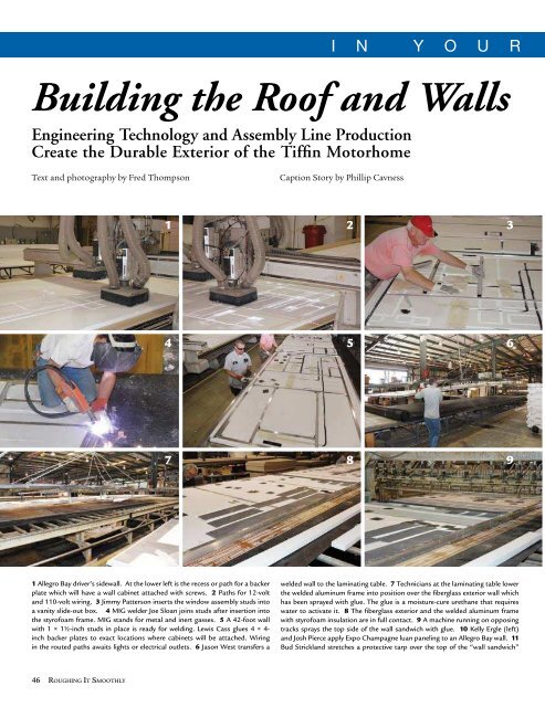
I n Y o u r C o r n e rBuilding the Roof and WallsEngineering Technology and Assembly Line ProductionCreate the Durable Exterior of the <strong>Tiffin</strong> MotorhomeText and photography by Fred ThompsonCaption Story by Phillip CavnessWWhen I see a new <strong>Tiffin</strong> motorhome, I notice the paint job andthe interesting designs. I check out the contours of the front andback caps, the LED lights, the slide-outs. Then, I go inside to fullyexperience the floorplan, the decor, the comfort level, the lighting,the conveniences. Immediately, I am looking forward to thetest drive. As I listen to the guttural tones of the 400 hp dieselengine, I anticipate the smooth surge of power as the Allegro Busglides out of the parking lot onto the highway. Its handling onthe highway is effortless: 25 tons — it’s almost too easy.Returning to the parking lot, I take a careful tour of thecoach with my notebook. All at the same time, it is a visual, tac-tile, physical experience. Ceramic tile, the smooth finish of finequality furniture, the suede in the valances, the softness of Ultraleather,the sharper images in hi-def television, the qualityof solid surface countertops, the 8-way power captain’s chair,and the list goes on.But what is so easy to overlook in a <strong>Tiffin</strong> coach is the infrastructure.It starts with the solid steel welded sub-floor withthe outrigger members to fully support the coach all the way toboth outer walls. A story on the welding shop two years ago revealedthat <strong>Tiffin</strong> <strong>Motorhomes</strong> uses on the average 400 poundsmore steel in a coach’s sub-floor system than any competitor.1 2 31011124 5 61314157 8 91617181 Allegro Bay driver’s sidewall. At the lower left is the recess or path for a backerplate which will have a wall cabinet attached with screws. 2 Paths for 12-voltand 110-volt wiring. 3 Jimmy Patterson inserts the window assembly studs intoa vanity slide-out box. 4 MIG welder Joe Sloan joins studs after insertion intothe styrofoam frame. MIG stands for metal and inert gasses. 5 A 42-foot wallwith 1 × 1½-inch studs in place is ready for welding. Lewis Cass glues 4 × 4-inch backer plates to exact locations where cabinets will be attached. Wiringin the routed paths awaits lights or electrical outlets. 6 Jason West transfers awelded wall to the laminating table. 7 Technicians at the laminating table lowerthe welded aluminum frame into position over the fiberglass exterior wall whichhas been sprayed with glue. The glue is a moisture-cure urethane that requireswater to activate it. 8 The fiberglass exterior and the welded aluminum framewith styrofoam insulation are in full contact. 9 A machine running on opposingtracks sprays the top side of the wall sandwich with glue. 10 Kelly Ergle (left)and Josh Pierce apply Expo Champagne luan paneling to an Allegro Bay wall. 11Bud Strickland stretches a protective tarp over the top of the “wall sandwich”prior to moving it into the stack press. The wall receives 5 to 10 pounds of pressureper square inch for 22 minutes in the four-tier press. 12 A tarp-covered wallis shown in the stack press just prior to lowering to begin the pressure curingprocess. The system was the first 48-foot stack press ever built by BSI in Yakima,Washington. 13 Bud Strickland and Kelly Ergle (left) work opposite HankWoodard to position pre-cut luan panels over the white naugahide soft-touchceiling material. Each panel is pre-drilled for barrel lights and A/C ducts. Thewhite naugahide is placed over a clean tarp to prevent any glue or debris marks.14 Using the same construction techniques for the roof structure, tubular steelframing is pressed into routed styrofoam channels for welding. A/C ducts andelectrical conduits are installed in routed channels and large back plates areglued on top to hold screws for all of the equipment mounted on the roof. AllenHoward routs the hole for a roof-mounted HVAC system. 15 Phyllis Garrisoninstalls wiring harnesses in the electrical pathways of the roof system cut with theCNC router. 16 After spraying the luan with glue, John Dowdy (left) and HankWoodard lower the styrofoam-insulated steel frame with A/C ducts and wiring46 Roughing It SmoothlyIn Your Corner 47