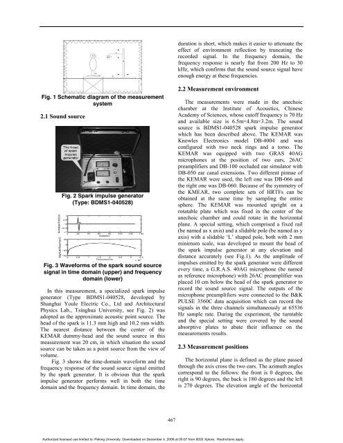
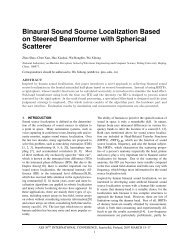
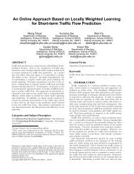
duration is short, which makes it easier to attenuate theeffect <strong>of</strong> environment reflection by truncating therecorded signal. In the frequency domain, thefrequency response is nearly flat from 200 Hz to 30kHz, which confirms that the sound source signal haveenough energy at these frequencies.Fig. 1 Schematic diagram <strong>of</strong> the measurementsystem2.1 Sound sourceFig. 2 Spark impulse generator(Type: BDMS1-040528)Fig. 3 Waveforms <strong>of</strong> the spark sound sourcesignal in time domain (upper) and frequencydomain (lower)In this measurement, a specialized spark impulsegenerator (Type BDMS1-040528, developed byShanghai Youle Electric Co., Ltd and ArchitecturalPhysics Lab., Tsinghua University, see Fig. 2) wasadopted as the approximate acoustic point source. Thehead <strong>of</strong> the spark is 11.3 mm high and 10.2 mm width.The nearest distance between the center <strong>of</strong> theKEMAR dummy-head and the sound source in thismeasurement was 20 cm, in which situation the soundsource can be taken as a point source from the view <strong>of</strong>volume.Fig. 3 shows the time-domain waveform and thefrequency response <strong>of</strong> the sound source signal emittedby the spark generator. It is obvious that the sparkimpulse generator performs well in both the timedomain and the frequency domain. In time domain, the2.2 Measurement environmentThe measurements were made in the anechoicchamber at the Institute <strong>of</strong> Acoustics, ChineseAcademy <strong>of</strong> Sciences, whose cut<strong>of</strong>f frequency is 70 Hzand available size is 6.5m×4.8m×3.2m. The soundsource is BDMS1-040528 spark impulse generatorwhich has been described above. The KEMAR wasKnowles Electronics model DB-4004 and wasconfigured with two neck rings and a torso. TheKEMAR was equipped with two GRAS 40AGmicrophones at the position <strong>of</strong> two ears, 26ACpreamplifiers and DB-100 occluded ear simulator withDB-050 ear canal extensions. Two different pinnae <strong>of</strong>the KEMAR were used, the left one was DB-066 andthe right one was DB-060. Because <strong>of</strong> the symmetry <strong>of</strong>the KMEAR, two complete sets <strong>of</strong> HRTFs can beobtained at the same time by sampling the entiresphere. The KEMAR was mounted upright on arotatable plate which was fixed in the center <strong>of</strong> theanechoic chamber and could rotate in the horizontalplane. A special setting, which comprised a fixed rail(be named as x axis) and a slidable pole (be named as yaxis) with a slidable ‘L’ shaped pole, both with 2 mmminimum scale, was developed to mount the head <strong>of</strong>the spark impulse generator at any elevation anddistance accurately (see Fig.1). As the amplitude <strong>of</strong>impulses emitted by the spark generator were differentevery time, a G.R.A.S. 40AG microphone (be namedas reference microphone) with 26AC preamplifier wasplaced 10 cm below the head <strong>of</strong> the spark generator torecord the sound source signal. The outputs <strong>of</strong> themicrophone preamplifiers were connected to the B&KPULSE 3560C data acquisition which can record thesignals in the three channels simultaneously at 65536Hz sample rate. During the experiment, the turntableand the special setting were covered by the soundabsorptive plates to abate their influence on themeasurements results.2.3 Measurement positionsThe horizontal plane is defined as the plane passedthrough the axis cross the two ears. The azimuth anglescorrespond to the follows: the front is 0 degrees, theright is 90 degrees, the back is 180 degrees and the leftis 270 degrees. The elevation angle <strong>of</strong> the horizontal467Authorized licensed use limited to: Peking University. Downloaded on December 4, 2008 at 05:07 from IEEE Xplore. Restrictions apply.
plane is 0 degrees. Negative elevation means that thesound source position was below the horizontal plane,positive denotes it was above that plane and the pointdirectly overhead was the 90 degrees elevation. Thedistance is defined from the midpoint <strong>of</strong> axis cross twoears <strong>of</strong> the dummy-head to the head <strong>of</strong> the sparkgenerator.This measurement was carried out at eight distanceswhich were 20, 30, 40, 50, 75, 100, 130 and 160 cmrespectively. Within proximal region, the interval issmaller because the variance <strong>of</strong> HRTFs in this area ismuch more dramatically than that in the distal region.At each distance, the spherical space around theKEMAR was sampled at elevations from -40 to 90degrees with 10 degrees interval. At each elevation, afull 360 degrees <strong>of</strong> azimuth was sampled in equal sizedincrements. Table 1 shows azimuth increment step(Step) and the number <strong>of</strong> samples (Num.) at everyelevation. Therefore at each distance, 793 locationsHRTFs were measured and 6344 HRTFs weremeasured totally.Table 1 The measurement positions2.4 Experimental procedureThe measurement procedure is described in Fig. 4.Measuring the impulse response <strong>of</strong> this system yieldsthe impulse response <strong>of</strong> the combined systemconsisting <strong>of</strong> the impulse generator (BDMS1-040528),the G.r.a.s. 40AG microphone with 26 ACpreamplifiers, B&K PULSE 3560C data acquisitionsystem, the anechoic chamber where the measurementswere made and most importantly, the response <strong>of</strong> theKEMAR with its accessories. Most room reflects wereavoid by the anechoic chamber and sponge plateswhich covered on the measurement setting. Theremainder <strong>of</strong> the room reflects were avoided byensuring that any reflections occur well after the headresponse time. The non-uniform spectrum <strong>of</strong> the pulsegenerator was compensated by using the signals, whichwere recorded by the left ear and the right earmicrophones, dividing the signal recorded by thereference microphone. The frequency responses <strong>of</strong> thethree microphones employed were almost identical.Fig. 4 HRTRs database generation procedureThe measurement was conducted in the order <strong>of</strong>distance, elevation and azimuth. That means, at first,HRTFs was measured at all azimuths with a fixedelevation and a fixed distance, which named as anazimuth-set. After that, the elevation was changed andanother azimuth-set <strong>of</strong> HRTFs were measured. Afterall the HRTFs at that distance have been measured, thedistance was changed and all the steps above wererepeated until all the distances were accomplished. Themeasurement procedure was described in detail asfollows:Given the elevation and distance, the coordinate <strong>of</strong>the sound source in the x axis and y axis could becalculated and the head <strong>of</strong> the spark impulse generatorwas set to the proper position. Prior to each azimuthsetmeasurement, the 0 degrees azimuth was confirmedby adjusting KEMAR to the position where the timedelays from the sound source to each ear were same.After the 0 degrees azimuth was marked, the HRTFswere measured by rotating KEMAR to each azimuthdegree. At each position, the spark generator emitted 5impulses continuously and the three microphonesrecorded simultaneously. These three recorded signalswere divided into 5 sets as the following two steps.First, found five maximum values <strong>of</strong> the referencechannel signal, each corresponds to every impulse.Second, the first maximum value sample was pickedout and the sample which was 64 samples earlier thanit was referred as the beginning point, the 1024 pointsfollowing the beginning sample were reserved as thesound source signal. The signals at the same time inthe other two corresponding channels were reserved asthe left ear signal and the right ear signal respectively.These three signals were viewed as a set. The sameprocessing was executed to the other four maximumvalues. Then the five sets <strong>of</strong> signals were used tocompute the HRTFs and the <strong>Head</strong>-Related ImpulseResponses (HRIRs) which are the inverse Fouriertransform <strong>of</strong> HRTFs. The reason <strong>of</strong> choosing 1024samples as the length <strong>of</strong> the signals (whose duration isabout 15 ms) is that such duration can ensure thereflection and diffraction signals, caused by the head,ears and torso, are reserved.468Authorized licensed use limited to: Peking University. Downloaded on December 4, 2008 at 05:07 from IEEE Xplore. Restrictions apply.