

Triple Band GPS Trap Loaded Inverted L Antenna Array - Mitre
Triple Band GPS Trap Loaded Inverted L Antenna Array - Mitre
Triple Band GPS Trap Loaded Inverted L Antenna Array - Mitre

You also want an ePaper? Increase the reach of your titles
YUMPU automatically turns print PDFs into web optimized ePapers that Google loves.
A single inverted L antenna typically has an<br />
elliptically polarized far field pattern, with both<br />
vertical and horizontal polarization components<br />
provided by the short vertical element and the<br />
much longer horizontal element. To achieve Right<br />
Hand Circular Polarization (RHCP) over a large<br />
portion of the upper hemisphere, as needed for<br />
receiving signals from the various <strong>GPS</strong> satellites,<br />
the four inverted L antenna elements of this array<br />
are arranged around a square at 90° intervals as<br />
shown in Figure 1 and excited with the equal<br />
amplitudes but with a relative phase difference of<br />
0°, -90°, -180°, and -270° (or +90°). This type of<br />
phase distribution between the array elements was<br />
obtained by means of a compact microstrip feed<br />
network consisting of a 180° “rat race” hybrid, the<br />
two outputs of which were each connected to<br />
compact, surface mounted 90° hybrids. This type<br />
of feed excitation provides good RHCP gain for<br />
the inverted L antenna array over much of the<br />
upper hemisphere allowing it to acquire <strong>GPS</strong><br />
satellites at elevation angles as low as 10°.<br />
Acquisition of the low elevation <strong>GPS</strong> satellites<br />
allows for a lower RMS position error in range.<br />
The input impedance of the inverted L antenna can<br />
be brought to resonance by adjusting the<br />
horizontal length “l” and the vertical height “h”,<br />
such that h + l ≈ λ /4, where λ is the wavelength<br />
[4,5]. The antenna array can be made to resonate<br />
in the L1 <strong>GPS</strong> frequency band by placing an RF<br />
trap tuned to 1.5754 GHz at an appropriate<br />
position along the horizontal arm of each of the<br />
four inverted L elements of the array. The trap<br />
load presents a very high impedance in the L1 band<br />
at the point in the antenna where the filter is<br />
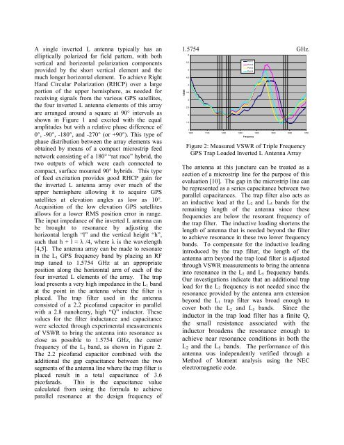
placed. The trap filter used in the antenna<br />
consisted of a 2.2 picofarad capacitor in parallel<br />
with a 2.8 nanohenry, high “Q” inductor. These<br />
values for the filter inductance and capacitance<br />
were selected through experimental measurements<br />
of VSWR to bring the antenna into resonance as<br />
close as possible to 1.5754 GHz, the center<br />
frequency of the L1 band, as shown in Figure 2.<br />
The 2.2 picofarad capacitor combined with the<br />
additional the gap capacitance between the two<br />
segments of the antenna line where the trap filter is<br />
placed result in a total capacitance of 3.6<br />
picofarads. This is the capacitance value<br />
calculated from using the formula to achieve<br />
parallel resonance at the design frequency of<br />
1.5754 GHz.<br />
VSWR<br />
6<br />
5.5<br />
5<br />
4.5<br />
4<br />
3.5<br />
3<br />
2.5<br />
2<br />
1.5<br />
Port 1<br />
Port 2<br />
Port 3<br />
Port 4<br />
1<br />
1000 1100 1200 1300 1400 1500 1600<br />
Frequency<br />
Figure 2: Measured VSWR of <strong>Triple</strong> Frequency<br />
<strong>GPS</strong> <strong>Trap</strong> <strong>Loaded</strong> <strong>Inverted</strong> L <strong>Antenna</strong> <strong>Array</strong><br />
1700<br />
The antenna at this juncture can be treated as a<br />
section of a microstrip line for the purpose of this<br />
evaluation [10]. The gap in the microstrip line can<br />
be represented as a series capacitance between two<br />
parallel capacitances. The trap filter also acts as<br />
an inductive load at the L2 and L5 bands for the<br />
remaining length of the antenna since these<br />
frequencies are below the resonant frequency of<br />
the trap filter. The inductive loading shortens the<br />
length of antenna that is needed beyond the filter<br />
to achieve resonance in these two lower frequency<br />
bands. To compensate for the inductive loading<br />
introduced by the trap filter, the length of the<br />
antenna arm beyond the trap load filter is adjusted<br />
through VSWR measurements to bring the antenna<br />
into resonance in the L2 and L5 frequency bands.<br />
Our investigations indicate that an additional trap<br />
load for the L2 frequency is not needed since the<br />
resonance provided by the antenna arm extension<br />
beyond the L1 trap filter was broad enough to<br />
cover both the L2 and L5 bands. Since the<br />
inductor in the trap load filter has a finite Q,<br />
the small resistance associated with the<br />
inductor broadens the resonance enough to<br />
achieve near resonance conditions in both the<br />
L2 and the L5 bands. The performance of this<br />
antenna was independently verified through a<br />
Method of Moment analysis using the NEC<br />
electromagnetic code.