VA BIM GUIDE - Office of Construction and Facilities Management
VA BIM GUIDE - Office of Construction and Facilities Management
VA BIM GUIDE - Office of Construction and Facilities Management
You also want an ePaper? Increase the reach of your titles
YUMPU automatically turns print PDFs into web optimized ePapers that Google loves.
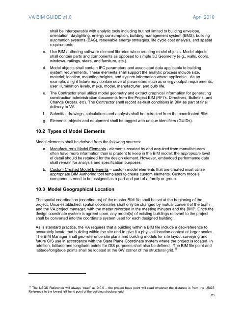
<strong>VA</strong> <strong>BIM</strong> <strong>GUIDE</strong> v1.0 April 2010shall be interoperable with analytic tools including but not limited to building envelope,orientation, daylighting, energy consumption, building management system (BMS), buildingautomation systems (BAS), renewable energy strategies, life cycle cost analysis, <strong>and</strong> spatialrequirements.c. Use <strong>BIM</strong> authoring s<strong>of</strong>tware element libraries when creating model objects. Model objectsshall contain parts <strong>and</strong> components as opposed to simple 3D Geometry (e.g., walls, doors,windows, railings, stairs, <strong>and</strong> furniture, etc.).d. Model objects shall contain IFC parameters <strong>and</strong> associated data applicable to buildingsystem requirements. These elements shall support the analytic process include size,material, location, mounting heights, <strong>and</strong> system information where applicable. As anexample, a light fixture may contain several parameters such as energy output requirements,user illumination levels, make, model, manufacturer, <strong>and</strong> bulb life.e. The Contractor shall utilize model geometry <strong>and</strong> extract graphical information for generatingconstruction administration documents from the Project <strong>BIM</strong> (RFI’s, Directives, Bulletins, <strong>and</strong>Change Orders, etc). The Contractor shall record as-built conditions in <strong>BIM</strong> as part <strong>of</strong> finaldelivery to <strong>VA</strong>.f. Submittal drawings, calculations <strong>and</strong> analysis shall be extracted from the coordinated <strong>BIM</strong>.g. Elements, objects <strong>and</strong> equipment shall be tagged with unique identifiers (GUIDs).10.2 Types <strong>of</strong> Model ElementsModel elements shall be derived from the following sources:a. Manufacturer’s Model Elements - elements created by <strong>and</strong> acquired from manufacturers<strong>of</strong>ten have more information than is prudent to keep in the <strong>BIM</strong> model; the appropriate level<strong>of</strong> detail should be retained for the design element. However, embedded performance datashall remain for analysis <strong>and</strong> specification purposes.b.Custom Created Model Elements – custom model elements that are created must utilizeappropriate <strong>BIM</strong> Authoring tool templates to create custom elements. Custom modelscomponents need to be assigned as a part <strong>and</strong> part <strong>of</strong> a family or group.10.3 Model Geographical LocationThe spatial coordination (coordinates) <strong>of</strong> the master <strong>BIM</strong> file shall be set at the beginning <strong>of</strong> theproject. Once established, spatial coordinates shall only be changed by mutual consent <strong>of</strong> the team<strong>and</strong> the <strong>VA</strong> project manager, with the matter recorded in the meeting minutes <strong>and</strong> the BMP. Once thedesign coordinate system is agreed upon, any model(s) <strong>of</strong> existing buildings relevant to the projectshall be converted into the coordinate system used for each designed building.As is st<strong>and</strong>ard practice, the <strong>VA</strong> requires that a building within a <strong>BIM</strong> file include a geo-reference toaccurately locate that building within the site <strong>and</strong> to give it a physical location context at larger scales.The <strong>BIM</strong> Manager shall geo-reference site plans <strong>and</strong> building models for site layout surveying <strong>and</strong>future GIS use in accordance with the State Plane Coordinate system where the project is located. Inaddition, latitude <strong>and</strong> longitude points for GIS purposes shall also be defined. The <strong>BIM</strong> file point <strong>and</strong>latitude/longitude points shall be located at the SW corner <strong>of</strong> the structural grid. 1515 The USGS Reference will always “read” as 0,0,0 – the project base point will read whatever the distance is from the USGSReference to the lowest left h<strong>and</strong> point <strong>of</strong> the building structural grid.20


