Compact cylinders ADN/AEN, to ISO 21287 - Allied Automation, Inc.
Compact cylinders ADN/AEN, to ISO 21287 - Allied Automation, Inc.
Compact cylinders ADN/AEN, to ISO 21287 - Allied Automation, Inc.

You also want an ePaper? Increase the reach of your titles
YUMPU automatically turns print PDFs into web optimized ePapers that Google loves.
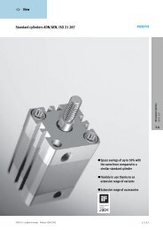
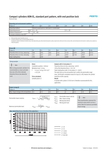
<strong>Compact</strong> <strong>cylinders</strong> <strong>ADN</strong>-EL, standard port pattern, with end position lockTechnical dataOperating and environmental conditionsPis<strong>to</strong>n ∅ 20 25 32 40 50 63 80 100Operating mediumFiltered compressed air, lubricated or unlubricatedOperating pressure [bar] 2.5 … 10 1.5 … 10Ambient temperature 1) [°C] –20 … +80Corrosion resistance class CRC 2) 21) Note operating range of proximity sensors2) Corrosion resistance class 2 <strong>to</strong> Fes<strong>to</strong> standard 940 070Components subject <strong>to</strong> moderate corrosion stress. Externally visible parts with primarily decorative surface requirements which are in direct contact with a normal industrial environment or media such as coolants orlubricating agentsForces [N]Pis<strong>to</strong>n ∅ 20 25 32 40 50 63 80 100Theoretical force at 6 bar, advancing 188 295 483 754 1178 1870 3016 4712Theoretical force at 6 bar, retracting 141 247 415 686 1057 1750 2827 4524Static holding force 250 500 2000 5000Sizing example-H- NoteWhen sizing pneumatic <strong>cylinders</strong> it isrecommended as a basic principlethat only 50% of the indicatedtheoretical forces (see above) beused.Given:Installation position = VerticalWorkpiece load = 44 kgF = m x g = 44 kg x 9.81 m/s 2= 431.6 NTo be calculated:Suitable pis<strong>to</strong>n ∅Analysiswith32mmpis<strong>to</strong>n∅:Theoretical force at 6 bar, advancing = 483 N50% of the theoretical force = 241.5 NStatic holding force with 32 mm pis<strong>to</strong>n ∅ =500NThe static force on the end position lock is within the permissible range(max. 500 N) with a workpiece load of 44 kg (431.6 N), however the cylinderwould be at 89% capacity.Result:A cylinder with a pis<strong>to</strong>n ∅ of 40 mm is therefore recommended for thisapplication.Impact energy [J]Pis<strong>to</strong>n ∅ 20 25 32 40 50 63 80 100Max. impact energy at the end positions 0.2 0.3 0.4 0.7 1 1.3 1.8 2.5Permissible impact velocity:Maximum permissible load:2xE perm.v perm. = mdead + m loadm load = 2xE perm.v 2− m deadv perm.E perm.m deadm loadPermissible impact velocityMax. impact energyMoving load (drive)Moving work load-H- NoteThese specifications represent themaximum values which can be reached.Note the maximum permittedimpact energy.Max. lateral force Fq as a function of the projection x∅ 20∅ 25∅ 32/40∅ 50/63∅ 80/10048 Internet: www.fes<strong>to</strong>.com/catalogue/...Subject <strong>to</strong> change – 2010/02