Roll Crown Specifications - Menges Roller Company, Inc.
Roll Crown Specifications - Menges Roller Company, Inc.
Roll Crown Specifications - Menges Roller Company, Inc.

You also want an ePaper? Increase the reach of your titles
YUMPU automatically turns print PDFs into web optimized ePapers that Google loves.
The Basic Theory<br />
of <strong>Crown</strong>ing<br />
Industrial <strong>Roll</strong>ers<br />
Written by<br />
Matthew <strong>Menges</strong> &<br />
Javier Carreon<br />
Please visit us at www.mengesroller.com<br />
260 Industrial Dr., Wauconda, Il 60084-1077 ▼ (847) 487-8877 Fax (847) 487-8897
<strong>Roll</strong>ers that are crowned are utilized by many industrial manufacturers. These<br />
companies are in the paper, film and foil converting industry. As a roller manufacturer,<br />
specifying a crown on a roller has to be taken with caution. Failure to do so may lead to<br />
problems and costly errors. Let us first establish the definition of a crown with respect<br />
to the roller industry. A crown is a shape or diameter profile necessary to compensate for<br />
deflection in order to obtain a uniform nip pressure distribution. (See Figure 1).<br />
FIGURE 1<br />
<strong>Roll</strong> crowning is intended to ensure proper web alignment and mainly to counter<br />
the effects of deflection. In a simple nip system, roller deflection is one of the main<br />
reasons for nip variations across the width of the roll face. This is primarily evident in<br />
all end loaded rollers. The roll will deflect or bend away from the nip, which causes<br />
pinching at the ends as seen in Figure 2.<br />
FIGURE 2<br />
The Basic Theory of <strong>Crown</strong>ing<br />
Industrial <strong>Roll</strong>ers<br />
¥<br />
¢<br />
<strong>Crown</strong>/2<br />
¥<br />
¢<br />
<strong>Roll</strong>er deflection is bending due to its dimensions, material, and the load being<br />
applied to the roll in its particular application. Therefore, roll crowning is one common<br />
method of reducing the nip variation caused by roller deflection. The other benefit of<br />
crowning a roll is that it will yield improved product quality. And more importantly<br />
crowning helps the roll covering last longer, increases the rubber life and helps reduce<br />
machine down time.<br />
As discussed earlier, specifying a crown on a roller has to be taken with caution.<br />
This is especially true when grinding or cutting an accurate crown. It is such a difficult<br />
¥<br />
¢<br />
260 Industrial Dr., Wauconda, Il 60084-1077 ▼ (847) 487-8877 Fax (847) 487-8897
process that if one compromises the shape/profile, it will cause more problems than<br />
not crowning at all. The amount of crown needed is usually very small and within a<br />
magnitude of a few mils (.001”). The amount of crown (barrel shape) is calculated from<br />
beam deflection formulas. The shape of a crown is nominally the shape of a beam<br />
deflected under a uniformly distributed load as shown below in Figure 3.<br />
FIGURE 3<br />
8<br />
DEFLECTION<br />
Utilizing the basic beam principle, roller specifications, and end user operating<br />
load requirements, a roller manufacturer can recommend a crown requirement for a<br />
roll. This process is achieved through modern computerized grinding machines. A program<br />
takes the deflection formula or tabulated values to produce the correct shape.<br />
The most commonly used crown angle is a 70 deg cosine angle. The reason<br />
behind this is that 70 degrees on each side of a cosine curve shows a close approximation<br />
to the deflection shape of a uniformly loaded simple beam (refer to Figure 4). The<br />
second most widely used crown angle is the 90 deg cosine angle. This specification is<br />
used for heavily loaded rollers with great lengths or unique header designs.<br />
FIGURE 4<br />
Cosine Curve<br />
a<br />
¥ DEFLECTION ¥<br />
UNIFORM LOAD<br />
Deflected Shape<br />
70 degrees 70 degrees<br />
A theoretical crown will equalize the nip pressure but the results should be<br />
checked. First, the actual diameter as measured by a Pi-tape or other means should be<br />
checked in at least 10 to 20 evenly spaced stations (in the cross machine direction).<br />
What is being measured is the target crown shape and magnitude across the width of<br />
the roll face. Second, the nip profile can be checked using nip impression paper and<br />
other techniques that are available. Nip impression paper behaves like carbon (or carbonless)<br />
paper which turns color when enough pressure has been applied to it.<br />
The static nip impression test is one of the easiest and safest methods that can<br />
be performed. The procedure for this test is to cut paper the width of the machine and<br />
a<br />
260 Industrial Dr., Wauconda, Il 60084-1077 ▼ (847) 487-8877 Fax (847) 487-8897
about 4-12” wide. Center the paper under the nip and flatten against the smooth roller.<br />
Then, load nip to operating values and hold for a minute. Finally, unload the nip and<br />
remove the paper to examine the impression. Figure 5 & 6 shows how a static nip test<br />
is applied as well as how to interpret your results from the actual impression taken at<br />
the nip.<br />
In a dynamic nip impression test the impression paper is applied similarly to<br />
the static test. The main difference is that the paper is applied just upstream of the nip.<br />
The nip is then loaded to the operating/test conditions and while loaded, the machine<br />
is briefly engaged at a controlled speed until the paper is completely pulled through<br />
the nip. Please see Figure 5 & 6 for the procedure and interpretation of the impression<br />
taken.<br />
FIGURE 5<br />
FIGURE 6<br />
Good<br />
Static Nip Impression<br />
¥<br />
<strong>Crown</strong> Too Low for Given Load<br />
<strong>Crown</strong> Too High for Given Load<br />
Unbalanced Loading or Misaligned<br />
Banding – <strong>Roll</strong>er Wear, Grinding<br />
Good<br />
Dynamic Nip Impression<br />
1<br />
¥<br />
<strong>Crown</strong> Too Low for Given Load<br />
<strong>Crown</strong> Too High for Given Load<br />
Unbalanced Loading or Misaligned<br />
Banding – <strong>Roll</strong>er Wear, Grinding<br />
260 Industrial Dr., Wauconda, Il 60084-1077 ▼ (847) 487-8877 Fax (847) 487-8897<br />
a<br />
a<br />
2
There are other methods of checking nip impressions. One is using embossed<br />
foil, which is evaluated by reading the embossing elements flattened in the closed nip.<br />
This method of test is helpful when testing heated nip rolls. The embossed foil eliminates<br />
worrying about ink running, bleeding, or blotting that results in using carbon<br />
paper. Another popular form of crown evaluation is an electronic nip reader. This<br />
device converts the nip loading and variances into real time data. Its benefit is that one<br />
can quickly read and adjust roll alignment or loading at the start-up or at maintenance<br />
shut down. In summary, this electronic device in terms of crown adjustment has no<br />
real advantage over a static or dynamic nip impression test. This is due to the fact that<br />
crown correction is done outside the production machine or more precisely at a grinding<br />
shop.<br />
In review, the crown amount and profile can be determined or confirmed by<br />
utilizing the useful techniques that were covered above. The results from testing will<br />
confirm the following:<br />
• The need for a crown (on un-crowned rolls)<br />
• <strong>Crown</strong> accuracy (for crowned rolls)<br />
• <strong>Roll</strong> alignment quality<br />
• Actual nip width<br />
And as previously discussed determining the crown amount can be calculated<br />
using engineering equations following the basic beam principle. One can also use<br />
methods like Finite Element Analysis (F.E.A) or other engineering type software.<br />
The bottom line is that because of simplicity and cost effectiveness the nip impression<br />
paper technique will help determine whether the crown is correct. For a static nip<br />
impression test or embossed foil kit, the following formula can be used to determine<br />
the required crown.<br />
C=<br />
(We 2 –Wc 2 )(D1+D2)<br />
2xD1D2<br />
Where....<br />
C = Diametric crown deficiency (positive if too little crown, negative if too much crown)<br />
We = Nip width on the roll ends<br />
Wc = Nip width at the roll center<br />
D1 = Diameter of roller 1<br />
D2 = Diameter of roller 2<br />
260 Industrial Dr., Wauconda, Il 60084-1077 ▼ (847) 487-8877 Fax (847) 487-8897
A good amount of information has been covered so far in respect to roll crowning.<br />
But one very important fact has to be mentioned in regards to the nip load vs.<br />
crown.<br />
In Figure 2, there is an externally applied force at the ends of one of the rolls<br />
which actually provides the nip load. Therefore, the amount of deflection and as a<br />
result the crown amount is determined by the nominal nip load. There is a load (x)<br />
which determines the required crown (y), and thus a given crown (y) matches only the<br />
value of load (x). Any other load than the match load above will not provide uniform<br />
nip loading across the width. Consequently the problem in a simple nip system is that<br />
one can not change the nip load without negatively affecting the uniformity of the nip.<br />
This poses a big challenge when there are a number of different grades or products<br />
that must be run. But fortunately there are solutions to this problem and that<br />
would be deflection compensation techniques. These techniques include using a small<br />
roller on a large roller nip system, roller skewing, and using a specialty roller like a<br />
controlled crown roller. The end result is that these techniques are weak and provide<br />
only a limited range of adjustment. As a result, one will usually crown one of the rolls<br />
to the lightest load and use the above deflection techniques to achieve higher operating<br />
loads.<br />
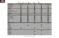
Below is an example of a crown report offered by <strong>Menges</strong> <strong>Roll</strong>er <strong>Company</strong>.<br />
<strong>Roll</strong> <strong>Crown</strong> <strong>Specifications</strong><br />
Input <strong>Crown</strong> Amount:<br />
0.030<br />
Inspection Station 700 For a 70<br />
Cam Angle Multiplier Target Shape<br />
0 Cosine <strong>Crown</strong> Only!<br />
0 00.000 0.0000<br />
1 0.0112 0.0003<br />
2 0.0451 0.0014<br />
3 0.1009 0.0030<br />
4 0.1778 0.0053<br />
5 0.2748 0.0082<br />
6 0.3904 0.0117<br />
7 0.5226 0.0157<br />
8 0.6699 0.0201<br />
9 0.8298 0.0249<br />
10 1.0000 0.0300<br />
<strong>Specifications</strong> needed to inspect crown:<br />
1. <strong>Crown</strong> amount - thousandths of inches of diameter<br />
2. Measured crown face - inches<br />
3. Cam angle - degrees<br />
4. Taper dubs - (if applicable) length x depth<br />
5. Centerline of crown should be centerline of roll<br />
6. Station Spacing = Measured crown face /20 spaces<br />
260 Industrial Dr., Wauconda, Il 60084-1077 ▼ (847) 487-8877 Fax (847) 487-8897
Commonly asked questions and answers.<br />
Web is not tracking properly and/or moves back and forth - Usually caused<br />
by uneven nip pressure or a wider nip area in one area of the web. The larger nip area<br />
pulls the substrate at a differing rate than the smaller area during nip lead in or nip<br />
lead out which causes the web to move back and forth.<br />
Excessive wrinkling or fold overs of the web or sheet – This is the same case<br />
as above. An uneven nip pressure causes an unbalanced pull because of an unequal<br />
dwell time of the substrate in the nip. This wrinkling can be made worse by downstream<br />
pull rollers actually pulling the web as the uneven nip is holding the substrate<br />
which creates wrinkles into the sheet.<br />
Uneven coating weight or laminating films are baggy in the center or the<br />
edges - Because the nip is uneven across the face, coatings are immediately affected<br />
lighter in the middle. This problem usually gets worse as operators add pressure to the<br />
ends of the rolls which cause deflection or bowing of the rolls. In laminating, the low<br />
center causes poor laminating film penetration which can be a cause of wrinkles<br />
pulled into the sheet as the deflection causes greater and greater nip pressure irregularities.<br />
Laminating is an art form. The nip pressure can be perfect but other factors like<br />
humidity can drive operators crazy. The point is that laminating will not tolerate<br />
uneven nip values.<br />
Tracking or steering is the issue - <strong>Crown</strong>s can be used to align or steer. If you<br />
can picture a band saw, the blade runs between to large wheels with a steep crown.<br />
The blade stays perfectly centered on top of a steep crown. For example, steel mills utilize<br />
crowns to steer the difficult web of steel which is stretched tight as a piano wire<br />
through coil lines as long as a football field.<br />
I crowned my rollers and I still have problems - A crown is a tool in your tool<br />
box. Used correctly it will solve problems. However it will not rectify a poor design or<br />
bad machine alignment. <strong>Crown</strong>s should be used in the design of rollers and equipment<br />
and not because of it. For example, a paper machine roll 25” in diameter 40’ in<br />
length can only be designed to work with crowning as an absolute preconceived notion<br />
from the start. Paper machine engineers don’t design their rollers to find out that they<br />
have uneven nip pressures and then go back to the drawing board.<br />
260 Industrial Dr., Wauconda, Il 60084-1077 ▼ (847) 487-8877 Fax (847) 487-8897
REFERENCES<br />
Mechanics of <strong>Roll</strong>ers by David Roisum TAPPI 1996<br />
Rubber <strong>Roll</strong>er Group, technical paper by John Slotten<br />
<strong>Roll</strong> <strong>Crown</strong> <strong>Specifications</strong> and Definitions, technical paper, TAPPI 1975<br />
Please visit us at www.mengesroller.com<br />
260 Industrial Dr., Wauconda, Il 60084-1077 ▼ (847) 487-8877 Fax (847) 487-8897