Common-Emitter Amplifier - MWFTR
Common-Emitter Amplifier - MWFTR
Common-Emitter Amplifier - MWFTR
- No tags were found...

You also want an ePaper? Increase the reach of your titles
YUMPU automatically turns print PDFs into web optimized ePapers that Google loves.
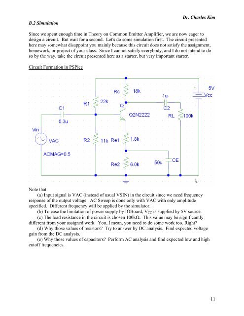
B.2 SimulationDr. Charles KimSince we spent enough time in Theory on <strong>Common</strong> <strong>Emitter</strong> <strong>Amplifier</strong>, we are now eager todesign a circuit. But wait for a second. Let's do some simulation first. The circuit presentedhere may somewhat disappoint you mainly because this circuit does not satisfy the assignment,homework, or project of your class. Since I cannot satisfy everybody, and I do not intend to doso by the way, take the circuit presented here as a starter, but very important starter.Circuit Formation in PSPiceNote that:(a) Input signal is VAC (instead of usual VSIN) in the circuit since we need frequencyresponse of the output voltage. AC Sweep is done only with VAC with only amplitudespecified. Different frequency will be applied by the simulator.(b) To ease the limitation of power supply by IOBoard, V CC is supplied by 5V source.(c) The load resistance in the circuit is chosen 100kΩ. This value may be significantlydifferent from your assigned work. You, I mean, you need to do some work too. Right?(d) Why those values of resistors? Try to answer by DC analysis. Find expected voltagegain from the DC analysis.(e) Why those values of capacitors? Perform AC analysis and find expected low and highcutoff frequencies.11