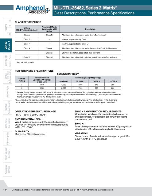
<strong>Amphenol</strong><strong>Aerospace</strong><strong>MIL</strong>-<strong>DTL</strong>-<strong>26482</strong>, <strong>Series</strong> 2, <strong>Matrix</strong> ®Class Descriptions, Performance SpecificationsOptions High SpeedEMI Filter Printed5015 83723 III <strong>26482</strong> 38999OthersFiber OpticsTransient Circuit Board26500 Pyle Crimp RearContacts Release <strong>Matrix</strong> <strong>Matrix</strong> Pyle <strong>Matrix</strong> 2 SJT I II IIICLASS DESCRIPTIONSMilitary<strong>MIL</strong>-<strong>DTL</strong>-<strong>26482</strong>, <strong>Series</strong> 2<strong>Amphenol</strong>/<strong>Matrix</strong>Commercial MB1<strong>Series</strong>DescriptionClass L Class R Aluminum shell, electroless nickel finish, fluid resistantClass E – Inactive, superceded by Class L*Class R – Inactive, superceded by Class L*Class A Class A Aluminum shell, black non-conductive anodized finish, fluid resistant– Class G Stainless steel shell, passivated, fluid resistantClass W Class W Aluminum shell, olive drab cadmium plated, corrosion/fluid resistant* Ref. <strong>MIL</strong>-<strong>DTL</strong>-<strong>26482</strong>PERFORMANCE SPECIFICATIONSServiceRatingRecommendedOperating AC Voltageat Sea LevelSERVICE RATINGS**Test Voltage AC (RMS), 60 cpsSea Level 50,000 ft. 70,000 ft. 110,000 ft.I 600 1,500 500 375 200II 1,000 2,300 750 500 200** Service Rating is comparable to MS rating A. Miniature connectors rated Service Rating I will provide a minimum flashovervoltage at sea level of 2,000 volts AC (RMS). Service Rating II is comparable to MS Service Rating D, and will provide a minimumflashover voltage of 2,800 volts AC (RMS) at sea level.Please note that the electrical data given is not an establishment of electrical safety factors. This is left entirely in the designer’shands, as he can best determine which peak voltage, switching surges, transients, etc. can be expected in a particular circuit.OPERATING TEMPERATURE RANGE–65°C (–85°F) to 200°C (392°F)ENVIRONMENTAL SEALWired, mated connectors with the specified accessoryattached will meet the altitude immersion test specifiedin <strong>MIL</strong>-<strong>DTL</strong>-<strong>26482</strong>.DURABILITYMinimum of 500 mating cycles.SHOCK AND VIBRATION REQUIREMENTSWhen tested as follows, the connector shall sustain nophysical damage, or electrical discontinuity exceedingone microsecond.SHOCK:Pulse of an approximate half sine wave of 300g magnitudewith duration of 3 milliseconds applied in three axes.VIBRATION:Sixteen hours of random vibration having a range of 50 to2,000 Hz with a 41.7G peak level.114 Contact <strong>Amphenol</strong> <strong>Aerospace</strong> for more information at 800-678-0141 • www.amphenol-aerospace.com
<strong>MIL</strong>-<strong>DTL</strong>-<strong>26482</strong>, <strong>Series</strong> 2, <strong>Matrix</strong> ®How to Order<strong>Amphenol</strong><strong>Aerospace</strong><strong>MIL</strong>-<strong>DTL</strong>-<strong>26482</strong>,<strong>Series</strong> 2Step 1. Military Connector Type1. 2. 3. 4. 5. 6. 7.ConnectorTypeConnectorStyleServiceClassShell Size/InsertArrangementContactTypeAlternateRotation of InsertModificationNumber<strong>MIL</strong>ITARY MS 3470 W 12-10 P W NACOMMERCIAL MB1 0 W 12-10 P W (xxx)MSDesignates Military StandardStep 2. Select a Connector StyleDesignates3470 Wall Mount Receptacle with Narrow Flange3472 Wall Mount Receptacle with Wide Flange3471 Cable Connecting Receptacle3474 Jam Nut Receptacle3476 Straight Plug3475 Straight Plug with RFI Grounding FingersStep 3. Select a Service ClassLAWDesignatesAluminum shell, electroless nickel finish, fluidresistant insertAluminum shell, black anodized finish, nonconductivefluid resistant insertAluminum shell, olive drab cadmium plated, fluidresistant insertNote: For stainless steel shell, passivated, order by <strong>Amphenol</strong> ® /<strong>Matrix</strong> ® commercial Class G.Class L inactivates classes E and R (Ref. <strong>MIL</strong>-<strong>DTL</strong>-<strong>26482</strong>)Step 4. Select a Shell Size & InsertArrangement from chart on page 111.Shell Size & Insert Arrangements are on pages 111First number represents Shell Size, second number isthe Insert Arrangement.Step 5. Select a Contact TypePSADesignatesPin ContactsSocket ContactsLess PinsB Less SocketsUse A & B only when other than a full complement of powercontacts is to be installed.Step 6. Select an Alternate Rotation of Insert“W”, “X”, “Y”, “Z” designate that insert is rotated in its shellfrom normal position. No letter required for normal (norotation) position. See page 111 for description of alternatepositions.For ordering information on accessories, such as protectioncaps and backshell hardware, contact <strong>Amphenol</strong><strong>Aerospace</strong>, Sidney, NY.Step 1. Commercial Connector TypeMB1Designates <strong>Amphenol</strong> ® /<strong>Matrix</strong> ® BayonetCoupling ConnectorStep 2. Select a Connector StyleDesignates0 Wall Mount Receptacle with Narrow Flange1 Wall Mount Receptacle with Wide Flange3 Cable Connecting Receptacle4 Jam Nut Receptacle6 Straight Plug8 Straight Plug with RFI Grounding FingersStep 3. Select a Service ClassARGWDesignatesAluminum shell, black anodized finish, nonconductive,fluid resistant insertAluminum shell, electroless nickel finish, fluidresistant insertStainless steel shell, passivated, fluid resistantinsertAluminum shell, cadmium plated, olive drabfinish, fluid resistant insertStep 4. Select a Shell Size & InsertArrangement from chart on page 111.Shell Size & Insert Arrangements are on pages 111.First number represents Shell Size, second number isthe Insert Arrangement.Step 5. Select a Contact TypePSDesignatesPin ContactsSocket ContactsStep 6. Select an Alternate Rotation of Insert“W”, “X”, “Y”, “Z” designate that insert is rotated in its shellfrom normal position. No letter required for normal (norotation) position. See page 111 for description of alternatepositions.Step 7. Modification NumberConsult <strong>Amphenol</strong> <strong>Aerospace</strong>, Sidney, NY for information.For strain reliefs use the following codes:(189) E-nut M85049/31 configuration(190) Straight strain relief M85049/52 configuration(191) 90° strain relief M85049/51 configuration38999III II I SJT<strong>26482</strong> 83723 III 5015<strong>Matrix</strong> 2<strong>Matrix</strong> PyleCrimp RearRelease <strong>Matrix</strong>26500 PylePrintedCircuit BoardEMI FilterTransientFiber OpticsHigh SpeedContactsOptionsOthersContact <strong>Amphenol</strong> <strong>Aerospace</strong> for more information at 800-678-0141 • www.amphenol-aerospace.com115