Important Safeguards INSTALLATION MANUAL AUTOMATIC ...
Important Safeguards INSTALLATION MANUAL AUTOMATIC ...
Important Safeguards INSTALLATION MANUAL AUTOMATIC ...
- No tags were found...

You also want an ePaper? Increase the reach of your titles
YUMPU automatically turns print PDFs into web optimized ePapers that Google loves.
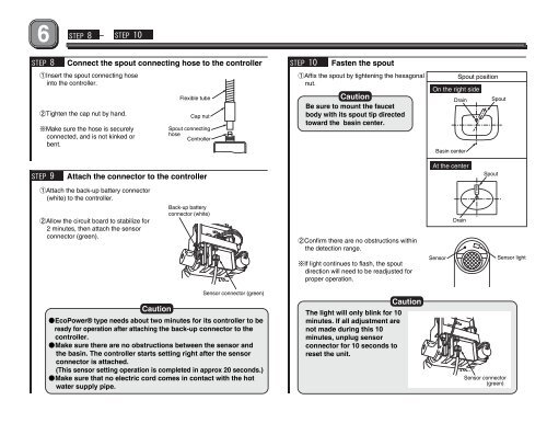
STEP 8 -STEP 10STEP 8Connect the spout connecting hose to the controller1Insert the spout connecting hoseinto the controller.2Tighten the cap nut by hand.※Make sure the hose is securelyconnected, and is not kinked orbent.Flexible tubeCap nutSpout connectinghoseControllerSTEP 10Fasten the spout1Affix the spout by tightening the hexagonalnut.CautionBe sure to mount the faucetbody with its spout tip directedtoward the basin center.Spout positionOn the right sideDrain SpoutBasin centerSTEP 9Attach the connector to the controllerAt the centerSpout1Attach the back-up battery connector(white) to the controller.2Allow the circuit board to stabilize for2 minutes, then attach the sensorconnector (green).Back-up batteryconnector (white)2Confirm there are no obstructions withinthe detection range.※If light continues to flash, the spoutdirection will need to be readjusted forproper operation.SensorDrainSensor lightCautionSensor connector (green)●EcoPower® type needs about two minutes for its controller to beready for operation after attaching the back-up connector to thecontroller.●Make sure there are no obstructions between the sensor andthe basin. The controller starts setting right after the sensorconnector is attached.(This sensor setting operation is completed in approx 20 seconds.)●Make sure that no electric cord comes in contact with the hotwater supply pipe.The light will only blink for 10minutes. If all adjustment arenot made during this 10minutes, unplug sensorconnector for 10 seconds toreset the unit.CautionSensor connector(green)