What is a Coil Connector? - Foxtronic
What is a Coil Connector? - Foxtronic
What is a Coil Connector? - Foxtronic

Create successful ePaper yourself
Turn your PDF publications into a flip-book with our unique Google optimized e-Paper software.
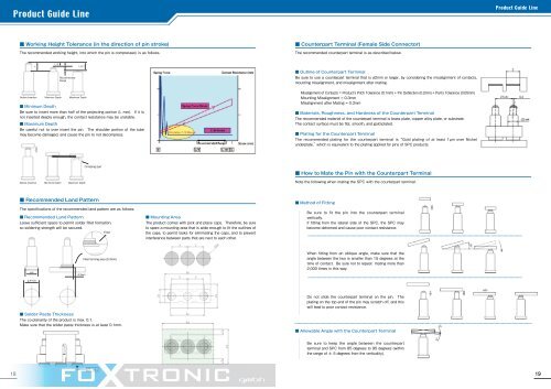
Product Guide LineProduct Guide Line■ Working Height Tolerance (in the direction of pin stroke)The recommended working height, into which the pin <strong>is</strong> compressed, <strong>is</strong> as follows.■ Counterpart Terminal (Female Side <strong>Connector</strong>)The recommended counterpart terminal <strong>is</strong> as described below.LL/2RecommendedRangeL-0.1■ Outline of Counterpart TerminalBe sure to use a counterpart terminal that <strong>is</strong> ø2mm or larger, by considering the m<strong>is</strong>alignment of contacts,mounting m<strong>is</strong>alignment, and m<strong>is</strong>alignment after mating.BeforeInsertion MinimumMIN Depth MaximumMAX Depth■ Minimum DepthBe sure to insert more than half of the projecting portion (L mm). If it <strong>is</strong>not inserted deeply enough, the contact res<strong>is</strong>tance may be unstable.■ Maximum DepthBe careful not to over insert the pin. The shoulder portion of the tubemay become damaged, and cause the pin to not decompress.M<strong>is</strong>alignment of Contacts = Product's Pitch Tolerance (0.1mm) + Pin Deflection (0.2mm) + Part's Tolerance (0.05mm)Mounting M<strong>is</strong>alignment = 0.3mmM<strong>is</strong>alignment after Mating = 0.3mm■ Materials, Roughness, and Hardness of the Counterpart TerminalThe recommended material of the counterpart terminal <strong>is</strong> brass plate, copper alloy plate, or substrate.The contact surface must be flat, smooth, and gold-plated.■ Plating for the Counterpart TerminalThe recommended plating for the counterpart terminal <strong>is</strong> “Gold plating of at least 1µm over Nickelunderplate,”which <strong>is</strong> equivalent to the plating applied for pins of SPC products. Crimping partBefore Insertion Minimum MIN Depth Maximum MAX Depth■ How to Mate the Pin with the Counterpart TerminalNote the following when mating the SPC with the counterpart terminal.■ Recommended Land PatternThe specifications of the recommended land pattern are as follows.■ Recommended Land PatternLeave sufficient space to permit solder fillet formation,so soldering strength will be secured. Fillet■ Mounting AreaThe product comes with pick and place caps. Therefore, be sureto spare a mounting area that <strong>is</strong> wide enough to fit the outlines ofthe caps, to permit tasks for eliminating the caps, and to preventinterference between parts that are next to each other.■ Method of FittingBe sure to fit the pin into the counterpart terminalvertically.If fitting from the lateral side of the SPC, the SPC maybecome deformed and cause poor contact res<strong>is</strong>tance.AA+0.60.3mmFillet forming area (0.3mm)When fitting from an oblique angle, make sure that theangle between the two <strong>is</strong> smaller than 15 degrees at thetime of contact. Be sure not to repeat mating more than2,000 times in th<strong>is</strong> way.Do not slide the counterpart terminal on the pin. Theplating on the top end of the pin may scratch off, and th<strong>is</strong>will lead to poor contact res<strong>is</strong>tance.■ Solder Paste ThicknessThe co-planarity of the product <strong>is</strong> max. 0.1.Make sure that the solder paste thickness <strong>is</strong> at least 0.1mm.■ Allowable Angle with the Counterpart TerminalBe sure to keep the angle between the counterpartterminal and SPC from 85 degrees to 95 degrees (withinthe range of ± 5 degrees from the verticality).1819