Overview ENGINE CONTROLS - INPUT SENSORS - Autoshop 101
Overview ENGINE CONTROLS - INPUT SENSORS - Autoshop 101
Overview ENGINE CONTROLS - INPUT SENSORS - Autoshop 101

Create successful ePaper yourself
Turn your PDF publications into a flip-book with our unique Google optimized e-Paper software.
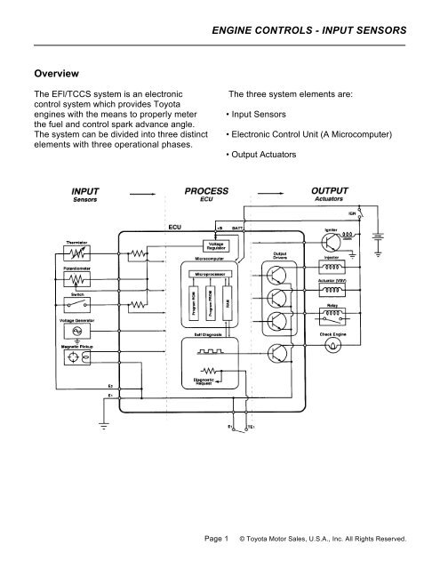
<strong>Overview</strong><br />
The EFl/TCCS system is an electronic<br />
control system which provides Toyota<br />
engines with the means to properly meter<br />
the fuel and control spark advance angle.<br />
The system can be divided into three distinct<br />
elements with three operational phases.<br />
<strong>ENGINE</strong> <strong>CONTROLS</strong> - <strong>INPUT</strong> <strong>SENSORS</strong><br />
The three system elements are:<br />
• Input Sensors<br />
• Electronic Control Unit (A Microcomputer)<br />
• Output Actuators<br />
Page 1 © Toyota Motor Sales, U.S.A., Inc. All Rights Reserved.
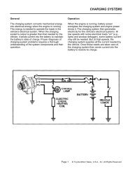
The electronic control system is responsible<br />
for monitoring and managing engine<br />
functions which were previously performed<br />
by mechanical devices like carburetors,<br />
vacuum, and centrifugal advance units. In an<br />
electronic control system, these functions<br />
are managed in three phases.<br />
• The input phase of electronic control allow<br />
the Electronic Control Unit (ECU) to monitor<br />
engine operating conditions, utilizing<br />
information from the input sensors.<br />
• The process phase of electronic control<br />
requires the ECU to use this input<br />
information to make operating decisions<br />
about the fuel and spark advance systems.<br />
• The output phase of electronic control<br />
requires the ECU to control the output<br />
actuators, the fuel injectors, and igniter to<br />
achieve the desired fuel metering and<br />
spark timing.<br />
In this chapter, we will explore the details of<br />
the electronic control system hardware and<br />
software. The chapter starts with a thorough<br />
examination of the system's input sensor<br />
circuits and the ECU power distribution<br />
system. It concludes with a closer look at the<br />
ECU process functions and the control<br />
strategy use( for optimum fuel metering and<br />
spark advance angle control.<br />
The Microcomputer<br />
The heart of the TCCS system is a<br />
microcomputer. A microcomputer is a<br />
device which receives information,<br />
processes it, and makes decisions based<br />
on a set of program instructions. The<br />
microcomputer exercises control over the<br />
output actuators to carry out these<br />
instructions.<br />
The use of microcomputers has taken the<br />
science of engine management into the<br />
space age by increasing the speed with<br />
<strong>ENGINE</strong> <strong>CONTROLS</strong> - <strong>INPUT</strong> <strong>SENSORS</strong><br />
which information can be processed and<br />
allowing the electronic control system to<br />
manage more engine functions. With the<br />
ability to process information so rapidly, the<br />
modern ECU is capable of carrying out its<br />
programmed instructions with extreme<br />
accuracy. Engine management can address<br />
virtually every condition the engine will<br />
encounter so that for any engine condition,<br />
the ECU will deliver optimum fuel and spark.<br />
Evolution of Toyota's Electronic Fuel<br />
Injection Systems<br />
Early Conventional EFI computers were first<br />
configured from analog circuits, and they<br />
controlled only fuel delivery and injection. The<br />
modem Electronic Control Units (ECU) utilize<br />
digital circuits and microprocessors which<br />
have served to improve EFI system<br />
capabilities.<br />
Modern TCCS engine controls, introduced to<br />
the U.S.A. market in 1983, are capable of<br />
managing fuel delivery, idle speed control<br />
(ISC), electronic spark advance (ESA), and<br />
emissions systems with extraordinary speed<br />
and accuracy.<br />
In the evolution of Toyota's fuel injection,<br />
three levels of electronic control refinements<br />
have taken place.<br />
• Conventional EFI<br />
• P7/EFI<br />
• EFI/TCCS<br />
The main difference between these systems<br />
is the capability of the ECU. These<br />
capabilities have grown from simple fuel<br />
control to the addition of self-diagnostics to<br />
the control of ignition spark advance and<br />
more. The following chart summarizes basic<br />
capabilities by system and can be used as a<br />
guide in identification and troubleshooting.<br />
Page 2 © Toyota Motor Sales, U.S.A., Inc. All Rights Reserved.
System identification is relatively simple.<br />
• The Conventional EFI system has no check<br />
engine light.<br />
• The P7/EFI system has a check engine<br />
light but has a mechanical advance<br />
distributor.<br />
• The EFI/TCCS system has a check engine<br />
light and an electronic advance distributor.<br />
<strong>ENGINE</strong> <strong>CONTROLS</strong> - <strong>INPUT</strong> <strong>SENSORS</strong><br />
The Input Sensors,<br />
Information Source for the ECU<br />
In an electronic control system, the ECU<br />
uses its sensors in much the same manner<br />
as we use our five senses. Our sense of<br />
touch tells us when things are hot or cold; our<br />
sense of hearing allows us to distinguish<br />
one sound from another; our sense of smell<br />
tells us when fresh coffee is brewing<br />
somewhere nearby. Sensors give the ECU<br />
similar abilities: the ability to feel the<br />
temperature of the engine coolant, to listen<br />
for the sound of detonation, and to smell the<br />
exhaust stream for the presence of sufficient<br />
oxygen.<br />
This lesson on input sensors will address<br />
how each major ECU input sensor circuit<br />
works. Each sensor circuit will be broken<br />
down so you can see its individual<br />
components: the sensor, electrical wiring,<br />
and the ECU.<br />
Page 3 © Toyota Motor Sales, U.S.A., Inc. All Rights Reserved.
<strong>Overview</strong><br />
The EFl/TCCS system is an electronic<br />
control system which provides Toyota<br />
engines with the means to properly meter<br />
the fuel and control spark advance angle.<br />
The system can be divided into three distinct<br />
elements with three operational phases.<br />
<strong>ENGINE</strong> <strong>CONTROLS</strong> - <strong>INPUT</strong> <strong>SENSORS</strong><br />
The three system elements are:<br />
• Input Sensors<br />
• Electronic Control Unit (A Microcomputer)<br />
• Output Actuators<br />
Page 4 © Toyota Motor Sales, U.S.A., Inc. All Rights Reserved.
Input Sensors Used in Basic<br />
Injection and Spark Calculation<br />
Engine Air Flow Sensing<br />
Vane Type Air Flow Meters<br />
(Vs, General Information)<br />
The vane type air flow meter is located in the<br />
air induction system inlet pipe between the<br />
air cleaner and the throttle body. It is<br />
composed of the measuring plate,<br />
compensation plate, return spring,<br />
potentiometer, and by-pass passage. The<br />
sensor also incorporates the idle mixture<br />
adjusting screw (factory sealed), the fuel<br />
pump switch, and the intake air temperature<br />
sensor (which will be addressed later in this<br />
lesson). Because intake air volume is a<br />
direct measure of the load placed on an<br />
engine, the vane type air flow meter provides<br />
the most important input to the ECU for fuel<br />
and spark calculations.<br />
When air passes through the air flow meter,<br />
it forces the measuring plate open to a point<br />
where it balances with the force of the return<br />
spring. The damping chamber and<br />
compensation plate prevent vibration of the<br />
measuring plate during periods of sudden<br />
intake air volume changes.<br />
The potentiometer, which is connected to the<br />
measuring plate and rotates on the same<br />
axis, converts the mechanical movement of<br />
the measuring plate into a variable voltage<br />
signal. Movement of the measuring plate and<br />
the analog voltage signal produced by this<br />
sensor are proportional to the volume of air<br />
entering the intake manifold.<br />
<strong>ENGINE</strong> <strong>CONTROLS</strong> - <strong>INPUT</strong> <strong>SENSORS</strong><br />
Vane Air How Meter Electrical Circuit<br />
The sensor movable contact is attached to<br />
the measuring plate and rides on a fixed<br />
resistor wired between the reference voltage<br />
input and the ground. As the volume of air<br />
entering the engine increases, the movable<br />
contact moves across the fixed resistor,<br />
causing a change in signal output voltage.<br />
There are two designs of vane air flow<br />
meters used on Toyota L type EFI systems.<br />
The first design generates a signal which<br />
varies from low voltage at low air volumes to<br />
high voltage at high air volumes. The second<br />
design sensor has opposite signal<br />
characteristics. These sensors also operate<br />
on different reference voltages. Both sensor<br />
designs integrate an intake air temperature<br />
sensor into the air flow meter.<br />
Page 5 © Toyota Motor Sales, U.S.A., Inc. All Rights Reserved.
First Design Vane Air How Meter<br />
The first design air flow meter is found on all<br />
Conventional EFI engines and many later<br />
model TCCS equipped engines. This sensor<br />
has an electrical connector with seven<br />
terminals, four of which are used for air flow<br />
measurement.<br />
Air Flow Sensor Terminal Identification<br />
(First Design Sensor)<br />
<strong>ENGINE</strong> <strong>CONTROLS</strong> - <strong>INPUT</strong> <strong>SENSORS</strong><br />
The air flow meter and ECU are wired as<br />
shown in the diagram. Signal characteristics<br />
are depicted by the accompanying graph. The<br />
use of battery voltage, VB, as a sensor input<br />
necessitates the use of the Vc terminal as a<br />
constant reference signal for the ECU. This is<br />
because battery voltage may change with<br />
variances in electrical load and ambient<br />
temperatures. Without the use of a constant<br />
reference voltage, these changes would<br />
cause a change in the Vs signal value<br />
recognized by the ECU.<br />
Page 6 © Toyota Motor Sales, U.S.A., Inc. All Rights Reserved.
Second Design Air How Meter<br />
The second design air flow meter was<br />
introduced on the '85 5M-GE engine, and its<br />
use expanded with many late model TCCS<br />
equipped engines. This sensor has an<br />
electrical connector with seven terminals,<br />
three of which are used for air flow<br />
measurement.<br />
Air Flow Sensor Terminal Identification<br />
(Second Design Sensor)<br />
<strong>ENGINE</strong> <strong>CONTROLS</strong> - <strong>INPUT</strong> <strong>SENSORS</strong><br />
The air flow meter and ECU are wired as<br />
shown in the diagram; signal characteristics<br />
are depicted by the accompanying graph. The<br />
use of a regulated 5 volt reference eliminates<br />
the need for the VB terminal with this sensor<br />
circuit.<br />
Resistors R1 and R2 provide self diagnostic<br />
capabilities and allow for a fail-safe voltage at<br />
the ECU in the event of an open circuit. These<br />
two resistors have a very high resistance<br />
value (relative to r1 and r2) and essentially<br />
have no electrical effect on the circuit under<br />
normal operating conditions. They will,<br />
however, affect the open circuit voltage<br />
measured on the Vs wire at the ECU.<br />
Page 7 © Toyota Motor Sales, U.S.A., Inc. All Rights Reserved.
Karman Vortex Air Flow Meter (Ks)<br />
The Karman vortex air flow meter is currently<br />
used on the 7M-GTE Toyota engine and the<br />
2JZ-GE and 1UZ-FE Lexus engines. It is<br />
located in the air induction system inlet pipe<br />
between the air cleaner and the throttle body.<br />
The sensor is composed of a photocoupler<br />
and mirror, a vortex generator, and an<br />
integrated circuit (IC) which together,<br />
measure the frequency of the vortices<br />
generated by air entering the intake system.<br />
When compared with the vane type air flow<br />
meter, the Karman vortex meter is smaller,<br />
lighter, and offers less restriction to incoming<br />
air. Similar to the vane type air meter, the<br />
<strong>ENGINE</strong> <strong>CONTROLS</strong> - <strong>INPUT</strong> <strong>SENSORS</strong><br />
Karman vortex meter integrates the intake air<br />
temperature sensor into the meter assembly.<br />
The sensor has an electrical connector with<br />
five terminals, three of which are used for air<br />
flow measurement.<br />
Karman Vortex Air Flow Meter<br />
Terminal Identification<br />
Page 8 © Toyota Motor Sales, U.S.A., Inc. All Rights Reserved.
The Karman vortex air flow meter and ECU<br />
are wired as shown in the diagram. Signal<br />
characteristics are represented by the<br />
illustration of the variable frequency square<br />
wave. Because of the pull-up resistor wired<br />
between the Vcc and Ks circuit, the Ks signal<br />
will go to 5 volts if the circuit is opened.<br />
<strong>ENGINE</strong> <strong>CONTROLS</strong> - <strong>INPUT</strong> <strong>SENSORS</strong><br />
When air passes through the air flow meter,<br />
the vortex generator creates a swirling of the<br />
air downstream. This swirling effect is<br />
referred to as a "Karman vortex." The<br />
frequency of this Karman vortex varies with<br />
the velocity of the air entering the air flow<br />
meter and other variables. The photocoupler<br />
and metal foil mirror are used to detect<br />
changes in these vortices.<br />
Page 9 © Toyota Motor Sales, U.S.A., Inc. All Rights Reserved.
The metal foil mirror is used to reflect light<br />
from the LED to the photo transistor. The foil<br />
is positioned directly above a pressure<br />
directing hole which causes it to oscillate<br />
with the changes in vortex frequency. As the<br />
mirror<br />
<strong>ENGINE</strong> <strong>CONTROLS</strong> - <strong>INPUT</strong> <strong>SENSORS</strong><br />
oscillates, the 5 volt Vcc reference is<br />
switched to ground by a photo transistor<br />
within the sensor. The resulting digital signal<br />
is a 5 volt square wave which increases in<br />
frequency in proportion to increases in intake<br />
air flow.<br />
Page 10 © Toyota Motor Sales, U.S.A., Inc. All Rights Reserved.
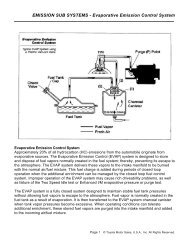
Manifold Absolute Pressure Sensor<br />
The manifold absolute pressure sensor<br />
(sometimes referred to as vacuum sensor)<br />
is used on engines equipped with D type<br />
EFI. It is typically located somewhere on the<br />
bulkhead with a vacuum line leading directly<br />
to the intake manifold. It measures intake air<br />
volume by monitoring changes in manifold<br />
absolute pressure, a function of engine load.<br />
<strong>ENGINE</strong> <strong>CONTROLS</strong> - <strong>INPUT</strong> <strong>SENSORS</strong><br />
The sensor consists of a piezoresistive<br />
silicon chip and an Integrated Circuit (IC). A<br />
perfect vacuum is applied to one side of the<br />
silicon chip and manifold pressure applied to<br />
the other side. When pressure in the intake<br />
manifold changes, the silicon chip flexes,<br />
causing a change in its resistance. The<br />
varying resistance of the sensor causes a<br />
change in signal voltage at the PIM (Pressure<br />
Intake Manifold) terminal.<br />
Page 11 © Toyota Motor Sales, U.S.A., Inc. All Rights Reserved.
The manifold absolute pressure sensor has<br />
an electrical connector with three terminals.<br />
Manifold Absolute Pressure Sensor<br />
Terminal Identification<br />
<strong>ENGINE</strong> <strong>CONTROLS</strong> - <strong>INPUT</strong> <strong>SENSORS</strong><br />
The sensor and ECU are wired as shown in<br />
the diagram. As manifold pressure increases<br />
(approaches atmospheric pressure) there is<br />
a proportionate increase in PIM signal<br />
voltage. This analog signal characteristic is<br />
depicted in the accompanying graph.<br />
TO check sensor calibration, signal voltage<br />
should be checked against the standards<br />
shown on the graph, and a voltage drop<br />
check should be performed over the entire<br />
operating range of the sensor.<br />
Page 12 © Toyota Motor Sales, U.S.A., Inc. All Rights Reserved.
Engine Speed and<br />
Crankshaft Angle Sensing<br />
On TCCS equipped engines, the Ne and G1<br />
signals inform the ECU of engine rpm and<br />
crankshaft angle. This information, along<br />
with information from the air flow or manifold<br />
pressure sensor, allows the ECU to<br />
calculate the engine's basic operating load.<br />
Based on measured load, basic injection<br />
and spark advance angle can be accurately<br />
calculated.<br />
Ne Signal (Number of Engine Revolutions)<br />
The Ne signal generator consists of a pickup<br />
coil and toothed timing rotor. The number of<br />
teeth on the signal timing rotor is determined<br />
by the system used. The Ne sensor<br />
produces an alternating current waveform<br />
<strong>ENGINE</strong> <strong>CONTROLS</strong> - <strong>INPUT</strong> <strong>SENSORS</strong><br />
signal and is of critical importance to the<br />
ECU. If this signal fails to reach the ECU, the<br />
engine will not run.<br />
G or G1 Signal (Group #1)<br />
The G signal generator is very similar to the<br />
Ne signal generator. The G1 signal<br />
represents the standard crankshaft angle<br />
and is used by the ECU to determine ignition<br />
and injection timing in relation to TDC.<br />
Depending on engine, there are different<br />
variations of Ne and G1 signal generators.<br />
The following illustrations show the<br />
relationship between the Ne and G1 signals<br />
and the different variations of signal<br />
generators.<br />
Page 13 © Toyota Motor Sales, U.S.A., Inc. All Rights Reserved.
<strong>ENGINE</strong> <strong>CONTROLS</strong> - <strong>INPUT</strong> <strong>SENSORS</strong><br />
Page 14 © Toyota Motor Sales, U.S.A., Inc. All Rights Reserved.
lGf Signal<br />
The IGf signal is generated by the igniter on<br />
EFI/TCCS systems. The ECU supplies a 5<br />
volt reference through a pull-up resistor to<br />
the lGf signal generation circuit in the igniter.<br />
When a spark plug fires, the IGf signal<br />
generation circuit pulls the five volts to<br />
ground, causing a pulse to be sensed at the<br />
ECU. One pulse is generated by the igniter<br />
for each ignition event which is carried out.<br />
IG Signal<br />
On Conventional EFI engines, the IG signal<br />
is used to inform the ECU of engine rpm.<br />
This signal is generated directly from the coil<br />
negative terminal or from an electrically<br />
equivalent point inside the igniter on the early<br />
<strong>ENGINE</strong> <strong>CONTROLS</strong> - <strong>INPUT</strong> <strong>SENSORS</strong><br />
The IGf signal confirms that ignition has<br />
actually occurred. In the event of a failure to<br />
trigger an ignition event, the ECU will shut<br />
down injector pulses to protect the catalyst<br />
from flooding with raw fuel. Typically this failsafe<br />
shutdown occurs within eight to eleven<br />
IGt signals after the IGf signal is lost. This<br />
condition can occur with any primary ignition<br />
system fault, an igniter failure, a problem with<br />
the IGf circuit wiring, or with a faulty ECU.<br />
P-7 2S-E engine. Conventional EFI engines<br />
do not use an Ne or G sensor and do not use<br />
an IGf signal. The IG signal is also used by<br />
the ECU to trigger injection pulses; therefore,<br />
if this signal is lost, the engine will stall for<br />
lack of injection pulse.<br />
Page 15 © Toyota Motor Sales, U.S.A., Inc. All Rights Reserved.
Input Sensors Used For Injection<br />
and Spark Corrections<br />
Water Temperature Sensor (THW)<br />
The water temperature sensor is typically<br />
located near the cylinder head water outlet. It<br />
monitors engine coolant temperature by<br />
means of an internally mounted thermistor.<br />
The thermistor has a negative temperature<br />
coefficient (NTC), so its resistance value<br />
decreases as coolant temperature rises.<br />
The accompanying resistance graph<br />
demonstrates this relationship.<br />
<strong>ENGINE</strong> <strong>CONTROLS</strong> - <strong>INPUT</strong> <strong>SENSORS</strong><br />
The water temperature sensor is required<br />
because fuel vaporization is less efficient<br />
when the engine is cold. Internal engine<br />
friction is also higher during cold operation,<br />
increasing operating load. The THW signal is<br />
used by the ECU to determine how much fuel<br />
enrichment correction is necessary to provide<br />
good cold engine performance. In addition to<br />
fuel calculations, the THW signal plays a<br />
major role is almost every other function that<br />
the ECU serves.<br />
Page 16 © Toyota Motor Sales, U.S.A., Inc. All Rights Reserved.
The water temperature sensor has a two<br />
terminal electrical connector attached to<br />
either end of the thermistor element.<br />
Water Temperature Sensor<br />
Terminal Identification<br />
<strong>ENGINE</strong> <strong>CONTROLS</strong> - <strong>INPUT</strong> <strong>SENSORS</strong><br />
The sensor and ECU are wired as shown in<br />
the diagram. Signal voltage characteristics<br />
are determined by the value of the pull-up<br />
resistor, located inside the ECU, either 2.7<br />
KΩ or 5 M. The graphs accompanying the<br />
diagram give approximate voltage<br />
specifications. To determine which pull-up<br />
resistor a particular ECU uses, refer to the<br />
technical reference charts in Appendix B of<br />
this book.<br />
Page 17 © Toyota Motor Sales, U.S.A., Inc. All Rights Reserved.
Air Temperature Sensor (THA)<br />
The air temperature sensor monitors the<br />
temperature of air entering the intake<br />
manifold by means of a thermistor. This<br />
thermistor is integrated within the air flow<br />
meter on L type systems and located in the<br />
intake air hose just downstream of the air<br />
cleaner on D type systems. It has the same<br />
resistance characteristics as the water<br />
temperature sensor.<br />
<strong>ENGINE</strong> <strong>CONTROLS</strong> - <strong>INPUT</strong> <strong>SENSORS</strong><br />
Page 18 © Toyota Motor Sales, U.S.A., Inc. All Rights Reserved.
This sensor has a two-terminal electrical<br />
connector attached to either end of the<br />
thermistor element.<br />
Air Temperature Sensor<br />
Terminal Identification<br />
<strong>ENGINE</strong> <strong>CONTROLS</strong> - <strong>INPUT</strong> <strong>SENSORS</strong><br />
The air temperature sensor and ECU are<br />
wired as shown in the diagram. Resistance<br />
and voltage signal characteristics are<br />
represented by the accompanying graphs.<br />
An intake air temperature monitor is<br />
necessary in the EFI system because the<br />
pressure and density of air changes with<br />
temperature. Because air is more dense<br />
when cold, the ECU factors intake air<br />
temperature into the fuel correction program.<br />
Page 19 © Toyota Motor Sales, U.S.A., Inc. All Rights Reserved.
Throttle Angle and<br />
Closed Throttle Sensing<br />
Throttle position sensors typically mount on<br />
the throttle body, directly to the end of the<br />
throttle shaft. Depending on engine and<br />
model year, Toyota EFI equipped engines<br />
use one of two different types of throttle<br />
position sensors. These sensors are<br />
categorized as on-off type and linear type.<br />
The linear type sensor is typically used on<br />
most late model Electronically Controlled<br />
Transmission (ECT) equipped vehicles.<br />
<strong>ENGINE</strong> <strong>CONTROLS</strong> - <strong>INPUT</strong> <strong>SENSORS</strong><br />
The on-off type sensor circuits can be further<br />
broken down into first and second design.<br />
This sensor is typically used on manual or<br />
non-ECT transmission equipped<br />
applications.<br />
All throttle sensors, regardless of design,<br />
supply the ECU with vital information about<br />
idle status and driver demand. This<br />
information is used by the ECU to make<br />
judgments about power enrichment,<br />
deceleration fuel cut-off, idle stability, and<br />
spark advance angle corrections.<br />
Page 20 © Toyota Motor Sales, U.S.A., Inc. All Rights Reserved.
On-Off Type Throttle Position<br />
Sensors (IDL & PSW)<br />
The on-off type throttle position sensor is a<br />
simple switch device which, depending on<br />
application, either pulls a reference voltage<br />
to ground or sends a battery voltage signal to<br />
the ECU. The on-off throttle position sensors<br />
are electrically wired to the ECU as shown in<br />
the accompanying diagrams.<br />
First Design On-Off Type Sensor<br />
The first design sensor is used on<br />
Conventional EFI engines. It utilizes a dual<br />
<strong>ENGINE</strong> <strong>CONTROLS</strong> - <strong>INPUT</strong> <strong>SENSORS</strong><br />
position contact which switches a battery<br />
voltage signal to either the IDL or PSW inputs<br />
at the ECU. This switching action causes the<br />
voltage signal at the ECU to go high<br />
whenever the switch contacts are closed.<br />
Referring to the voltage graph, IDL signal<br />
voltage is high when the throttle is closed<br />
and goes low when the throttle exceeds a 1.5'<br />
opening. PSW voltage is low until the throttle<br />
exceeds about a 70' opening; then it goes<br />
high.<br />
Page 21 © Toyota Motor Sales, U.S.A., Inc. All Rights Reserved.
Second Design On-Off Type Sensor<br />
The second design sensor, which is used<br />
on many late model TCCS equipped<br />
engines, utilizes a dual position contact to<br />
switch an ECU reference voltage to ground.<br />
This switching action causes the signal at<br />
the ECU to go low whenever the switch<br />
contacts are closed.<br />
Referring to the voltage graph, IDL signal<br />
voltage is low when the throttle is closed and<br />
goes high when the throttle exceeds a 1.5'<br />
opening. PSW voltage is high until the throttle<br />
opens to about 70’; then it goes low.<br />
<strong>ENGINE</strong> <strong>CONTROLS</strong> - <strong>INPUT</strong> <strong>SENSORS</strong><br />
The three wire electrical connector terminals<br />
are identified as follows.<br />
1 st and 2nd Design On-Off Throttle<br />
Position Sensor Terminal Identification<br />
Page 22 © Toyota Motor Sales, U.S.A., Inc. All Rights Reserved.
On '83 and '84 Cressidas/Supras and '83<br />
through '86 Camrys equipped with an<br />
Electronically Controlled Transmission<br />
(ECT), a modified sensor, which<br />
incorporates three additional signal wires<br />
designated L1, L2, and L3, is used. These<br />
signals represent throttle opening angles in<br />
between the 1.5' IDL and 70' PSW signals.<br />
The L1, L2, and L3 signals are used by the<br />
ECT system and are generated in a similar<br />
manner as the IDL and PSW signals on the<br />
2nd design sensor. The TCCS ECU only<br />
uses the IDL and PSW signals from this<br />
sensor.<br />
<strong>ENGINE</strong> <strong>CONTROLS</strong> - <strong>INPUT</strong> <strong>SENSORS</strong><br />
Linear Throttle Position Sensor (VTA)<br />
The linear throttle position sensor is<br />
mounted to the throttle body. It is composed<br />
of two movable contacts, a fixed resistor, and<br />
four electrical terminals. The two movable<br />
contacts move along the same axis as the<br />
throttle valve. One is used for the throttle<br />
opening angle signal (VTA) and the other for<br />
the closed throttle signal (IDL).<br />
Page 23 © Toyota Motor Sales, U.S.A., Inc. All Rights Reserved.
As the throttle opens, a potentiometer circuit<br />
converts the mechanical movement of the<br />
throttle valve into a variable voltage signal.<br />
The voltage produced by this sensor is<br />
proportional to the throttle valve opening<br />
angle.<br />
The Linear Throttle Position Sensor has an<br />
electrical connector with four terminals.<br />
Linear Throttle Position Sensor<br />
Terminal Identification<br />
<strong>ENGINE</strong> <strong>CONTROLS</strong> - <strong>INPUT</strong> <strong>SENSORS</strong><br />
The sensor and ECU are wired as shown in<br />
the diagram. As the throttle valve opens, the<br />
sensor VTA contact moves closer to the<br />
voltage source, causing a signal voltage<br />
increase.<br />
At closed throttle, the IDL contact is held<br />
closed. This pulls the IDL signal circuit to<br />
ground. As the throttle opens, the IDL contact<br />
breaks, causing the digital IDL signal voltage<br />
to go from low to high. These signal<br />
characteristics are depicted in the<br />
accompanying graph.<br />
Resistors R1 and R2 provide self diagnostic<br />
capabilities and allow for a fail-safe voltage at<br />
the ECU in the event of an open circuit. These<br />
two resistors have a very high resistance<br />
value and essentially have no electrical effect<br />
on the circuit under normal operating<br />
conditions. They will, however, affect the open<br />
circuit voltage measured on the VTA wire at<br />
the ECU.<br />
Page 24 © Toyota Motor Sales, U.S.A., Inc. All Rights Reserved.
Exhaust Oxygen Content Sensing (OX1)<br />
Exhaust oxygen sensors are used on Toyota<br />
EFI and EFI/TCCS equipped engines to<br />
provide air/fuel ratio feedback information to<br />
the ECU. This information is used to<br />
constantly adjust the air/fuel ratio to<br />
stoichiometry during warm idle and cruise<br />
operating conditions. The stoichiometric<br />
air/fuel ratio delivers one pound of fuel for<br />
each 14.7 pounds of air entering the intake<br />
manifold and results in the most efficient<br />
combustion and catalyst operation. When the<br />
electronic control system is using<br />
information from the oxygen sensor to adjust<br />
air/fuel ratio, the system is said to be<br />
operating in closed loop.<br />
Exhaust oxygen sensor efficiency is<br />
dependent upon its operating temperature.<br />
The sensor will only generate an accurate<br />
signal when it has reached its minimum<br />
operating temperature of 750'F. Therefore,<br />
the oxygen sensor is typically located in the<br />
exhaust stream at the manifold collector.<br />
This location is close enough to the exhaust<br />
valves to maintain adequate operating<br />
temperature under most driving conditions<br />
and allows a representative exhaust sample<br />
from all cylinders.<br />
<strong>ENGINE</strong> <strong>CONTROLS</strong> - <strong>INPUT</strong> <strong>SENSORS</strong><br />
Open and Closed Loop Operation<br />
In addition to promoting efficient combustion<br />
and catalyst operation, a stoichiometric<br />
air/fuel ratio also promotes excellent fuel<br />
economy. This relatively lean mixture is<br />
desirable during cruise and idle operation;<br />
however, other operating conditions often<br />
require a richer air/fuel ratio. When the<br />
electronic control system ignores signals<br />
from the oxygen sensor and does not correct<br />
the air/fuel ratio to 14.7:1, the system is said<br />
to be operating in open loop.<br />
In order to prevent overheating of the catalyst<br />
and ensure good driveability, open loop<br />
operation is required under the following<br />
conditions:<br />
• During engine starting<br />
• During cold engine operation<br />
• During moderate to heavy load operation<br />
• During acceleration and deceleration<br />
During open loop operation, the ECU ignores<br />
information from the exhaust oxygen sensor<br />
and bases fuel injection duration calculations<br />
exclusively on the other input sensors.<br />
Page 25 © Toyota Motor Sales, U.S.A., Inc. All Rights Reserved.
Exhaust Oxygen Sensors<br />
Toyota engines utilize two different types of<br />
oxygen sensors. The zirconium dioxide sensor is<br />
used on all engines except the '90 and later 4A-GE<br />
Federal and 3VZ-E California 2WD truck engines.<br />
These two engines use a titania oxide sensor.<br />
To bring the system to closed loop operation more<br />
rapidly, many engines use a heated exhaust<br />
oxygen sensor. The heated sensor provides more<br />
accurate exhaust sampling during idle and low<br />
speed operation when exhaust temperatures are<br />
relatively low. Use of a heated sensor allows<br />
closed loop operation earlier during engine warmup<br />
cycles and also allows more flexibility in<br />
oxygen sensor location. These factors help in<br />
meeting strict exhaust emissions control<br />
standards.<br />
Engines produced for sale in California also<br />
incorporate a Sub-Oxygen Sensor which helps<br />
improve the efficiency of the catalyst system. This<br />
sensor is located after the catalyst and is used to<br />
fine tune the air/fuel ratio delivered by the<br />
injectors, helping to optimize catalyst efficiency.<br />
<strong>ENGINE</strong> <strong>CONTROLS</strong> - <strong>INPUT</strong> <strong>SENSORS</strong><br />
Zirconium Dioxide Sensor The zirconium dioxide<br />
oxygen sensor is an electro-chemical device<br />
which compares the oxygen content of the<br />
exhaust stream with the oxygen in an ambient air<br />
sample. It consists of a zirconium dioxide (Zr02)<br />
element sandwiched between two platinum<br />
electrodes.<br />
This sensor behaves very similar to a single cell<br />
battery. The electrodes act as the positive (+) and<br />
negative (-) plates, and the zirconium dioxide<br />
element acts as the electrolyte.<br />
Rich air/fuel ratio: If the oxygen concentration on<br />
the inside plate differs greatly from that on the<br />
outside plate, as it would with a rich air/fuel ratio,<br />
electrons will flow through the Zr02 element to the<br />
plate exposed to the high oxygen concentration.<br />
During rich operating conditions, the inside, or<br />
positive plate, is exposed to a much higher<br />
concentration of oxygen than the outside, or<br />
negative plate. This creates a difference in<br />
electrical potential, or voltage, which is measured<br />
by a comparator circuit in the E CU.<br />
Lean air/fuel ratio: When the air/fuel ratio<br />
becomes lean, the oxygen content of the exhaust<br />
gas increases significantly. Because both plates<br />
are now exposed to a relatively high concentration<br />
of oxygen, electrons balance equally between the<br />
two plates. This eliminates the electrical potential<br />
between the plates.<br />
Zirconium Dioxide Oxygen Sensor<br />
Operating Characteristics<br />
Page 26 © Toyota Motor Sales, U.S.A., Inc. All Rights Reserved.
Zr02 sensor voltage signal and ECU<br />
processing: The voltage signal produced by.<br />
the oxygen sensor is relatively small. During<br />
the richest operating conditions, this signal<br />
approaches 1000 millivolts (1 volt).<br />
The Zr02 oxygen sensor is wired as shown<br />
in the diagram. Voltage characteristics are<br />
depicted in the accompanying graph.<br />
As the voltage graph illustrates, the output of<br />
the Zr02 sensor acts almost like a switch. As<br />
the air/fuel ratio passes through the<br />
stoichiometric range, voltage rapidly<br />
switches from high to low.<br />
<strong>ENGINE</strong> <strong>CONTROLS</strong> - <strong>INPUT</strong> <strong>SENSORS</strong><br />
The ECU comparator circuit is designed to<br />
monitor the voltage from the sensor and<br />
send a digital signal to the microprocessor. If<br />
sensor voltage is above the comparator<br />
switch point, z 1/2 volt, the comparator output<br />
will be high. If the sensor voltage is below the<br />
comparator switch point, the comparator<br />
output will be low. The microcomputer<br />
monitors the output of the comparator to<br />
determine how much oxygen remains in the<br />
exhaust stream after combustion occurs.<br />
Page 27 © Toyota Motor Sales, U.S.A., Inc. All Rights Reserved.
Titania Oxide Sensor This four-terminal<br />
device is a variable resistance sensor with<br />
heater. It is connected in series between the<br />
OX+ reference and a fixed resistance located<br />
inside the ECU. This circuit operates<br />
similarly to a thermistor circuit.<br />
The properties of the thick film titania<br />
element are such that as oxygen<br />
concentration of the exhaust gas changes,<br />
the resistance of the sensor changes. As the<br />
sensor resistance changes, the signal<br />
voltage at the ECU also changes.<br />
TITANIA OXIDE SENSOR<br />
RESISTANCE CHARACTERISTICS<br />
The titania sensor and ECU are wired as<br />
shown in the diagram. A one-volt potential is<br />
supplied at all times to the OX+ terminal of<br />
the sensor. The resistance value of the<br />
sensor changes abruptly as the<br />
stoichiometric boundary is crossed. The<br />
accompanying voltage and resistance<br />
graphs depict these characteristics and their<br />
influence on OX signal voltage.<br />
<strong>ENGINE</strong> <strong>CONTROLS</strong> - <strong>INPUT</strong> <strong>SENSORS</strong><br />
The ECU comparator circuit is designed to<br />
monitor the voltage drop across R1. As the<br />
voltage drop across the sensor increases,<br />
the drop across R1 decreases and vice<br />
versa. This gives the OX signal voltage the<br />
same characteristic as the Zr02 sensor.<br />
If sensor voltage drop is low, as it would be<br />
with a rich mixture, OX signal voltage will be<br />
above the comparator switch point, 450<br />
millivolts, and the comparator output will be<br />
high. If the sensor voltage drop is high, OX<br />
signal voltage will be below the comparator<br />
switch point and the comparator output will<br />
be low.<br />
Page 28 © Toyota Motor Sales, U.S.A., Inc. All Rights Reserved.
Sub-Oxygen Sensor (OX2)<br />
The sub-oxygen sensor is used on California<br />
and some Federal engines. It is used to<br />
monitor the exhaust stream after the catalyst<br />
to determine if the air/fuel mixture is within<br />
the range for efficient converter operation.<br />
<strong>ENGINE</strong> <strong>CONTROLS</strong> - <strong>INPUT</strong> <strong>SENSORS</strong><br />
The sub-oxygen sensor is identical to the<br />
Zr02 main oxygen sensor located ahead of<br />
the catalyst. Information from this sensor is<br />
used by the ECU to fine tune the air/fuel ratio<br />
and improve emissions.<br />
Page 29 © Toyota Motor Sales, U.S.A., Inc. All Rights Reserved.
Oxygen Sensor Heater Circuits (HT)<br />
Oxygen sensors work very efficiently when<br />
the sensing element temperature is above<br />
750'F (400'C). At warm cruise, it is not difficult<br />
to maintain oxygen sensor temperatures at<br />
or above this point. However, when the<br />
engine is first started or when idling or when<br />
driving under very light load, the oxygen<br />
sensor can cool down, forcing the fuel<br />
system to return to open loop operation.<br />
The oxygen sensor heater control system<br />
maintains sensor accuracy by turning on the<br />
heater element whenever intake air volume<br />
is low (exhaust temperatures are low under<br />
these conditions). By heating the sensor<br />
electrically, sensor detection performance is<br />
enhanced.<br />
<strong>ENGINE</strong> <strong>CONTROLS</strong> - <strong>INPUT</strong> <strong>SENSORS</strong><br />
This allows feedback operation under<br />
conditions which might otherwise require<br />
open loop fuel control. The ECU monitors the<br />
following parameters and cycles the oxygen<br />
sensor heater on:<br />
• When intake air flow is below a given point.<br />
and<br />
• coolant temperature is above approximately<br />
32'F (O'C).<br />
• specified time has elapsed after starting.<br />
The oxygen sensor heater and ECU are<br />
wired as shown in the diagram. Whenever<br />
the above mentioned conditions are met, the<br />
ECU turns on the driver transistor to supply a<br />
ground path for heater current.<br />
Page 30 © Toyota Motor Sales, U.S.A., Inc. All Rights Reserved.
Other Inputs Affecting Injection<br />
and Spark Correction<br />
Engine Cranking Signal (STA)<br />
STA is a digital signal which is used by the<br />
ECU to determine if the engine is being<br />
cranked. The signal is generated at the ST1<br />
terminal of the ignition switch and is used by<br />
the ECU primarily to increase fuel injection<br />
volume during cranking.<br />
<strong>ENGINE</strong> <strong>CONTROLS</strong> - <strong>INPUT</strong> <strong>SENSORS</strong><br />
The STA circuit is wired to the ECU as shown<br />
in the diagram. The ECU will sense cranking<br />
voltage at the STA terminal whenever the<br />
ignition is switched to the "start" position as<br />
long as the neutral or clutch switch is closed.<br />
Page 31 © Toyota Motor Sales, U.S.A., Inc. All Rights Reserved.
Engine Detonation (Knock) Signal (KNK)<br />
Knock Sensor<br />
The knock sensor is a piezoelectric device<br />
mounted to the cylinder block which generates a<br />
voltage whenever it is exposed to vibration. When<br />
engine detonation occurs, vibration of the cylinder<br />
block causes the sensor to generate a voltage<br />
signal. The sensor signal varies in amplitude<br />
depending on the intensity of knock.<br />
Typically, detonation vibration occurs in the 7KHz<br />
range (7 thousand cycles per second). Knock<br />
sensor and ECU designs take advantage of this<br />
fact.<br />
There are two different types of knock sensors<br />
used on Toyota engines. The mass type sensor<br />
produces a voltage output over a wide input<br />
frequency range; however, its signal output is<br />
greatest at a vibration frequency of approximately<br />
7KHz. With this type of sensor, the ECU uses a<br />
filter circuit to distinguish between background<br />
noise and actual engine knock.<br />
The resonance type sensor is tuned into a very<br />
narrow frequency band and only produces a<br />
significant signal voltage when exposed to<br />
vibrations in the 7KHz range. The ECU requires<br />
less complicated filter circuitry with this type of<br />
sensor.<br />
<strong>ENGINE</strong> <strong>CONTROLS</strong> - <strong>INPUT</strong> <strong>SENSORS</strong><br />
ECU Detonation Control<br />
The ECU and knock sensor are wired as shown in<br />
the diagram. When engine detonation occurs, the<br />
ECU monitors knock sensor signal feedback to<br />
determine the degree of detonation taking place.<br />
This is accomplished by filtering out sensor signal<br />
voltage which does not go above preprogrammed<br />
amplitude parameters. Because other background<br />
noise and vibration cause some signal output from<br />
the knock sensor, the ECU is also programmed to<br />
filter out any signal which does not fall within<br />
certain frequency ranges.<br />
When the ECU judges that detonation is taking<br />
place, it retards ignition timing until the knocking<br />
stops. Timing is then advanced back to calculated<br />
value or, if detonation again begins, retarded again<br />
until detonation is stopped. In this manner, the<br />
ignition system can be operated at maximum<br />
efficiency, on the borderline of detonation, while<br />
avoiding an audible "ping." In the event that the ECU<br />
continues to sense detonation, timing retard is<br />
limited based on a clamp value stored in memory. If<br />
the ECU determines that the knock retard is not<br />
functional, it will enter a fail-safe mode and fix the<br />
retard angle to prevent engine damage.<br />
Page 32 © Toyota Motor Sales, U.S.A., Inc. All Rights Reserved.
Altitude Sensing (HAC)<br />
Some TCCS equipped engines like the 3F-E,<br />
3VZ-E (Cab and Chassis), and the 7M-GTE<br />
incorporate an altitude sensor in the TCCS<br />
system to shorten injection duration when<br />
the vehicle is operated at higher altitudes.<br />
<strong>ENGINE</strong> <strong>CONTROLS</strong> - <strong>INPUT</strong> <strong>SENSORS</strong><br />
Because the density of oxygen in the<br />
atmosphere is lower at high altitudes, the air<br />
volume measured by the air flow meter will<br />
not accurately represent actual oxygen<br />
entering the engine. This would result in a<br />
mixture which is excessively rich, causing<br />
emissions and driveability concerns.<br />
The HAC sensor is integrated with the ECU<br />
on the 3-FE, 3VZ-E, and 1989 and later 7M-<br />
GTE engines. It is remotely mounted behind<br />
the glove box on the '87 and '88 7M-GTE<br />
Supra. The remotely mounted HAC sensor is<br />
wired to the ECU exactly the same as the<br />
manifold pressure sensor is wired on D type<br />
EFI. In fact, the HAC sensor circuit is<br />
electrically the same as a manifold pressure<br />
sensor circuit. The HAC sensor simply<br />
measures atmospheric pressure rather than<br />
intake manifold pressure.<br />
The signal from the HAC circuit in the ECU is<br />
used to determine the fuel correction<br />
coefficient to be used after basic injection<br />
has been calculated. The accompanying<br />
graph represents how this correction factor<br />
affects final injection duration.<br />
Page 33 © Toyota Motor Sales, U.S.A., Inc. All Rights Reserved.
Stop Light Switch (STP)<br />
The stop light switch input to the ECU is<br />
used to modify the deceleration fuel cut<br />
program when the vehicle is braking.<br />
Whenever the STIR signal is high (brake<br />
pedal is depressed), fuel cutoff and<br />
resumption rpm is reduced to improve<br />
driveability characteristics of the vehicle.<br />
In the event the STP signal is lost, fuel cut<br />
will take place at the standard deceleration<br />
speed, causing an objectionable feel when<br />
fuel is canceled.<br />
<strong>ENGINE</strong> <strong>CONTROLS</strong> - <strong>INPUT</strong> <strong>SENSORS</strong><br />
The STP signal at the ECU will be low as<br />
long as the brake pedal is not applied. When<br />
the pedal is depressed, current flows through<br />
the normally open stop light switch to the<br />
stop lamps and the ECU, causing the STP<br />
voltage to go high.<br />
Page 34 © Toyota Motor Sales, U.S.A., Inc. All Rights Reserved.