257xR User's Guide - Xitron Technologies
257xR User's Guide - Xitron Technologies
257xR User's Guide - Xitron Technologies

You also want an ePaper? Increase the reach of your titles
YUMPU automatically turns print PDFs into web optimized ePapers that Google loves.
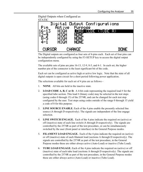
Configuring the Analyser 35Digital Outputs when Configured asSTATICThe Digital outputs are configured as four sets of 4-pins each. Each set of four pins canbe independently configured by using the F3-SETUP key to access the digital outputconfiguration menu.The available sets of pins are pins 16-13, 12-9, 8-5, and 4-1. In each set, the highernumber pin of the connector is the least significant bit of the code.Each set can be configured as active high or active low logic. Note that the state of alldigital outputs is open circuit for a short period following power application.The selections available for each set of 4 pins are as follows -1. NONE. All bits are held in the inactive state.2. LOAD CODE A, B, C or D. A 4-bit code representing the required load # for thespecified tube section. This load # (binary code) may be selected in the test steps(using codes 0 through 15) of the 2574R, and can be changed for each test stepconfigured by the user. Test steps using codes outside of the range 0 through 15 yielda code of 0 for this purpose.3. LINE SOURCE ENABLE. Each of the 4 pins enable the presently selected linesource (A through D respectively). The signals are independent of the line engageselection.4. LINE SWITCH ENGAGE. Each of the 4 pins indicate the required on (active) oroff (inactive) state of each line switch (A through D respectively). The signals arecontrolled by the 2574R as part of the test procedure, or can be simultaneouslyswitched by the user (front panel or interface) in the General Purpose modes.5. FILAMENT LOAD ENGAGE. Each of the 4 pins indicate the required on (active)or off (inactive) state of each filament load (sections A through D respectively). Thesignals are controlled by the 2574R as part of the test procedure, in the GeneralPurpose modes these are either always active (Auto-Load) or inactive (Tube Load).6. TUBE LOAD ENGAGE. Each of the 4 pins indicate the required on (active) or off(inactive) state of each tube load (sections A through D respectively). The signals arecontrolled by the 2574R as part of the test procedure, in the General Purpose modesthese are either always active (Auto-Load) or inactive (Tube Load).