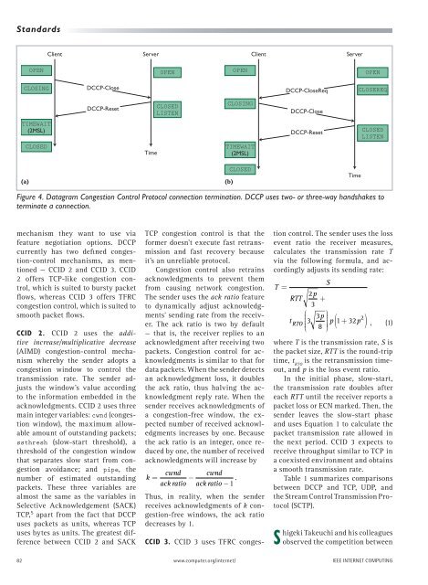
<strong>Transport</strong> <strong>Protocol</strong> <strong>with</strong> <strong>Congestion</strong> <strong>Control</strong> <strong>and</strong> <strong>Unreliability</strong>(seqno=2), <strong>and</strong> the server responds<strong>with</strong> packet(seqno=5 <strong>and</strong> ackno=2).Consequently, the client sendspacket(seqno=3 <strong>and</strong> ackno=5).During the transfer process, <strong>DCCP</strong>endpoints might use <strong>DCCP</strong>-Sync <strong>and</strong><strong>DCCP</strong>-SyncAck packets for synchronization.In Figure 3, suppose that the clientsends packets(seqno=10~101),<strong>and</strong> only packet(seqno=10) <strong>and</strong>packet(seqno=101) arrive at theserver, while the remaining packetsare lost. The server receivespacket(seqno=101), but this sequencenumber isn’t <strong>with</strong>in seqno’sexpected range. To synchronize thesequence numbers in the client, theserver immediately sends a <strong>DCCP</strong>-Sync packet <strong>and</strong> acknowledges receivingthe packet <strong>with</strong> ackno=101.When the client receives this <strong>DCCP</strong>-Sync packet, it immediately responds<strong>with</strong> a <strong>DCCP</strong>-SyncAck packet. Uponreceiving this packet, the serverchanges the expected range of seqnoto synchronize both sides.In contrast to TCP acknowledgments,<strong>DCCP</strong> acknowledgments havetwo distinguishing characteristics:they’re restricted by congestion control,<strong>and</strong> the sender must report itsacknowledgment reception to thereceiver in a timely manner. Eachacknowledgment has an ack vectoroption that the receiver uses to reportits packet reception to the sender.The vector comprises a series of8-bit blocks, including state (2 bits)<strong>and</strong> run length (6 bits). The vectorhas three defined states: received (0),received but <strong>with</strong> an explicit congestionnotification (ECN) mark (1), <strong>and</strong>not yet received (3). Run length representshow many consecutive packetsare in the given state.As the receiver gets more packets,it reports more receiving conditionsto the sender, thus causing the ackvector’s size to gradually increase.So, the sender must occasionallyreply to the receiver through theacks-of-acks, notifying the receiverabout which acknowledgments theClient<strong>DCCP</strong>-Data(seq1)<strong>DCCP</strong>-Data(seq2)<strong>DCCP</strong>-Ack(seq5, ack2)<strong>DCCP</strong>-DataAck(seq3, ack5)<strong>DCCP</strong>-Data(seq6).<strong>DCCP</strong>-Data(seq10)<strong>DCCP</strong>-Data(seq11).<strong>DCCP</strong>-Data(seq100)<strong>DCCP</strong>-Data(seq101)<strong>DCCP</strong>-Sync(seq7, ack101)<strong>DCCP</strong>-SyncAck(seq102, ack7)sender has received. As soon as thereceiver gets the acks-of-acks, itcan forget the receiving conditionsof packets that the sender has recognized,thereby reducing the ackvector’s size.<strong>DCCP</strong> features another importantoption, data drop, which letsthe sender clearly distinguish thecause of each packet loss. The datadrop option comprises a series of 8-bit blocks. The highest bit representswhether the receiver has successfullytransferred the received packetsto the application layer. Afterthe highest bit, a drop code of 3 bitsindicates any causes for the drop,including protocol constraints (0),application not listening (1), receiverbuffer (2), corrupt (3), <strong>and</strong> deliveredcorrupt (7). The remaining 4 bits arethe run length.Connection termination. Figure 4ashows the process by which <strong>DCCP</strong>terminates a connection. When theclient intends to terminate a connection,it sends a <strong>DCCP</strong>-Close packet.Upon receiving this, the server sendsServerTimeExpected seqno[10, 60]Seqno out of rangeSend syncExpected seqno[102, 152]Figure 3. Datagram <strong>Congestion</strong> <strong>Control</strong> <strong>Protocol</strong> data transfer. <strong>DCCP</strong> can use<strong>DCCP</strong>-Sync <strong>and</strong> <strong>DCCP</strong>-SyncAck packets to synchronize the sequence numbersof both sides.a <strong>DCCP</strong>-Reset packet to finish theconnection-termination process.When the client receives the <strong>DCCP</strong>-Reset packet, it terminates the connectionafter waiting for 2MSL. Theprocess by which the server intendsto terminate a connection is similarto the previous description: the serverfirst sends a <strong>DCCP</strong>-Close packet, thenthe client sends a <strong>DCCP</strong>-Reset packet,<strong>and</strong> finally the server waits in theTIMEWAIT state for 2MSL. In general,<strong>DCCP</strong> achieves the connection terminationprocedure <strong>with</strong> a <strong>DCCP</strong>-Closepacket <strong>and</strong> a <strong>DCCP</strong>-Reset packet,regardless of which side initializesthis process. However, the servercan decide to let the client remain inthe TIMEWAIT state. In this case, theserver first sends a <strong>DCCP</strong>-CloseReqpacket to the client; the remainder ofthe process is the same as the precedingcases, as in Figure 4b.<strong>Congestion</strong> <strong>Control</strong>Applications can select suitable congestioncontrol according to their requirements.The server <strong>and</strong> the clientcan negotiate the congestion-controlSEPTEMBER/OCTOBER 2008 81
St<strong>and</strong>ardsClientServerClientServerOPENOPENOPENOPENCLOSING<strong>DCCP</strong>-Close<strong>DCCP</strong>-CloseReqCLOSEREQ<strong>DCCP</strong>-ResetCLOSEDLISTENCLOSING<strong>DCCP</strong>-CloseTIMEWAIT(2MSL)<strong>DCCP</strong>-ResetCLOSEDLISTENCLOSEDTimeTIMEWAIT(2MSL)(a)(b)CLOSEDTimeFigure 4. Datagram <strong>Congestion</strong> <strong>Control</strong> <strong>Protocol</strong> connection termination. <strong>DCCP</strong> uses two- or three-way h<strong>and</strong>shakes toterminate a connection.mechanism they want to use viafeature negotiation options. <strong>DCCP</strong>currently has two defined congestion-controlmechanisms, as mentioned— CCID 2 <strong>and</strong> CCID 3. CCID2 offers TCP-like congestion control,which is suited to bursty packetflows, whereas CCID 3 offers TFRCcongestion control, which is suited tosmooth packet flows.CCID 2. CCID 2 uses the additiveincrease/multiplicative decrease(AIMD) congestion-control mechanismwhereby the sender adopts acongestion window to control thetransmission rate. The sender adjuststhe window’s value accordingto the information embedded in theacknowledgments. CCID 2 uses threemain integer variables: cwnd (congestionwindow), the maximum allowableamount of outst<strong>and</strong>ing packets;ssthresh (slow-start threshold), athreshold of the congestion windowthat separates slow start from congestionavoidance; <strong>and</strong> pipe, thenumber of estimated outst<strong>and</strong>ingpackets. These three variables arealmost the same as the variables inSelective Acknowledgement (SACK)TCP, 5 apart from the fact that <strong>DCCP</strong>uses packets as units, whereas TCPuses bytes as units. The greatest differencebetween CCID 2 <strong>and</strong> SACKTCP congestion control is that theformer doesn’t execute fast retransmission<strong>and</strong> fast recovery becauseit’s an unreliable protocol.<strong>Congestion</strong> control also retrainsacknowledgments to prevent themfrom causing network congestion.The sender uses the ack ratio featureto dynamically adjust acknowledgments’sending rate from the receiver.The ack ratio is two by default— that is, the receiver replies to anacknowledgment after receiving twopackets. <strong>Congestion</strong> control for acknowledgmentsis similar to that fordata packets. When the sender detectsan acknowledgment loss, it doublesthe ack ratio, thus halving the acknowledgmentreply rate. When thesender receives acknowledgments ofa congestion-free window, the expectednumber of received acknowledgmentsincreases by one. Becausethe ack ratio is an integer, once reducedby one, the number of receivedacknowledgments will increase bycwnd cwndk = −ack ratio ack ratio −1 .Thus, in reality, when the senderreceives acknowledgments of k congestion-freewindows, the ack ratiodecreases by 1.CCID 3. CCID 3 uses TFRC congestioncontrol. The sender uses the lossevent ratio the receiver measures,calculates the transmission rate Tvia the following formula, <strong>and</strong> accordinglyadjusts its sending rate:T =S2pRTT +3⎛ p ⎞tRTO3 3 p + p⎝⎜⎠⎟( 1 32 2 ) , (1)8where T is the transmission rate, S isthe packet size, RTT is the round-triptime, t RTOis the retransmission timeout,<strong>and</strong> p is the loss event ratio.In the initial phase, slow-start,the transmission rate doubles aftereach RTT until the receiver reports apacket loss or ECN marked. Then, thesender leaves the slow-start phase<strong>and</strong> uses Equation 1 to calculate thepacket transmission rate allowed inthe next period. CCID 3 expects toreceive throughput similar to TCP ina coexisted environment <strong>and</strong> obtainsa smooth transmission rate.Table 1 summarizes comparisonsbetween <strong>DCCP</strong> <strong>and</strong> TCP, UDP, <strong>and</strong>the Stream <strong>Control</strong> Transmission <strong>Protocol</strong>(SCTP).Shigeki Takeuchi <strong>and</strong> his colleaguesobserved the competition between82 www.computer.org/internet/ IEEE INTERNET COMPUTING