Commodore Free Magazine Issue #59 (PDF)
Commodore Free Magazine Issue #59 (PDF)
Commodore Free Magazine Issue #59 (PDF)
- No tags were found...

You also want an ePaper? Increase the reach of your titles
YUMPU automatically turns print PDFs into web optimized ePapers that Google loves.
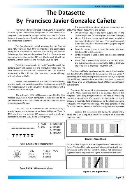
www.commodorefree.comThe DatasetteBy Francisco Javier Gonzalez CañeteThe <strong>Commodore</strong> 1530/1531 (C2N) was/is the peripheralused by the <strong>Commodore</strong> computers to store software inmagnetic tapes. It was the storage medium most used in Europebecause it was cheaper than the disk drive that was, at least,five times more expensive.The first datasette model appeared for the <strong>Commodore</strong>PET. There are four different models of the <strong>Commodore</strong>1530, but all of them share the same functionality and they arefully compatible between themselves. The first of the units wasintegrated in the <strong>Commodore</strong> PET and it had a black lid with fivebuttons, without a counter and without a Save led light.The first external model for the PET was black with fivebuttons, again without counter and without Save led light. Thenext model was also for the <strong>Commodore</strong> PET. This one waswhite with a black lid, but this time with counter althoughwithout a Save led light.Finally, the most common and most often sold versionwas the model that was developed for the <strong>Commodore</strong> VIC-20.This model was white with a silver lid, it had six buttons, with acounter and a Save led light.The last model (C2N 1531) was developed for the <strong>Commodore</strong>16/116 and Plus/4 computers. It was identical to itspredecessor but it was black in colour and the connector to thecomputer was different.The C2N 1530 is connected to the computer using aspecial six pins border connector as shown in Figure 4. The C2N1531 used a seven pin mini-DIN connector and is pin-by-pincompatible with the 1530 model (see Figure 5).The communication signals of these connectors areGND, VCC, Motor, Read, Write and Sense:· VCC and GND: They are the power supply pins for thedatasette (but not for the engine that moves the tape).· Motor: This is the control signal and power supply forthe engine that moves the tapes. This signal is controlledby the computer. When it is active (5V) the enginecan start working.· Read: This signal is used to send the serial data fromthe datasette to the computer.· Write: This signal is used to send the data to be storedin the tape.· Sense: This is a control signal that is active (0V) whenany button have been pressed in the C2N. In that way,the computer is informed about that fact.The Read and Write signals are used to transmit and receivethe data from the datasette to the computer and vice versa. Aserial frequency modulated protocol is used, that is, each pulsehas a different period and each duration represents a piece ofdata. There are a lot of loaders and each of them uses differentpulse lengths.The pulses that are sent from the computer to the datasetteusing the Write signal are stored in an analogue form in themagnetic tapes; using a magnetic head. This head is a metal ringthat is the core of a coil. If a current is applied to the coil, it willproduce a magnetic field proportional to the electromagneticinduction. This magnetic field aligns the tape particles in theform that they can be read in the future using the inverse process.Because the stored data are digital, the values finallysaved are 0 or 1. Figure 3 shows an example of a recordedmagnetic tape.Figure 3. Aligned headFigure 1. C2N 1530 connector pinoutThis way of storing data was very dependant of the mechanicfactor. The head has to be very well aligned; at least with thesame angle as the one that saved the tape, if not, some readingerrors could be presented. Figure 4 depicts this situation.Figure 2. C2N 1531 connector pinoutFigure 4. Bad aligned head.Page 25