


You also want an ePaper? Increase the reach of your titles
YUMPU automatically turns print PDFs into web optimized ePapers that Google loves.
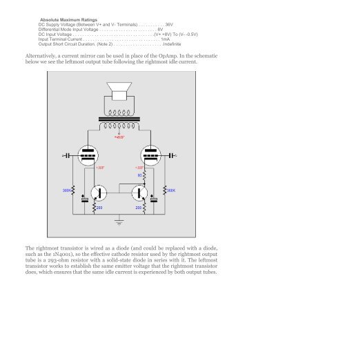
Absolute Maximum RatingsDC Supply Voltage (Between V+ and V- Terminals) . . . . . . . . . . . 36VDifferential Mode Input Voltage . . . . . . . . . . . . . . . . . . . . . . . . 8VDC Input Voltage . . . . . . . . . . . . . . . . . . . . . . . . . . . . . . . . . .(V+ +8V) To (V- -0.5V)Input Terminal Current . . . . . . . . . . . . . . . . . . . . . . . . . . . . . . . . 1mAOutput Short Circuit Duration. (Note 2) . . . . . . . . . . . . . . . . . . . . .IndefiniteAlternatively, a current mirror can be used in place of the OpAmp. In the schematicbelow we see the leftmost output tube following the rightmost idle current.The rightmost transistor is wired as a diode (and could be replaced with a diode,such as the 1N4001), so the effective cathode resistor used by the rightmost outputtube is a 293-ohm resistor with a solid-state diode in series with it. The leftmosttransistor works to establish the same emitter voltage that the rightmost transistordoes, which ensures that the same idle current is experienced by both output tubes.


