

industrial belt and drive preventive maintenance - Gates Corporation
industrial belt and drive preventive maintenance - Gates Corporation
industrial belt and drive preventive maintenance - Gates Corporation
- No tags were found...

You also want an ePaper? Increase the reach of your titles
YUMPU automatically turns print PDFs into web optimized ePapers that Google loves.
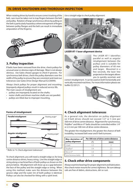
IV. Drive shutdown <strong>and</strong> thorough inspectionWhen rotating <strong>drive</strong>s by h<strong>and</strong> to ensure correct tracking of the<strong>belt</strong>, care must be taken not to trap fingers between the <strong>belt</strong><strong>and</strong> pulley. Rotation of large synchronous <strong>drive</strong>s by pulling onthe <strong>belt</strong> is particularly hazardous where entrapment of fingersbetween pulley flanges <strong>and</strong> the <strong>belt</strong> can result in immediateamputation of the finger(s).Use a straight edge to check pulley alignment.LASER AT-1 laser alignment device3. Pulley inspectionIf <strong>belt</strong>s have been removed from the <strong>drive</strong>, check pulleys forunusual wear or obvious signs of damage. Wear is not alwaysobvious. Use <strong>Gates</strong> sheave gauges to check V-grooves. Forsynchronous <strong>belt</strong> <strong>drive</strong>s, check the pulley diameters over thewidth of the pulley to ensure they are consistent <strong>and</strong> meet ourtolerances (see <strong>Gates</strong> Drive Design Manual E2/20099).Always check pulleys for proper alignment <strong>and</strong> mounting.Improperly aligned pulleys result in reduced service life.The main causes of misalignment are:• pulleys are improperly located on the shafts;• motor shafts <strong>and</strong> <strong>drive</strong>n machine shafts are not parallel;• pulleys are tilted due to improper mounting.The LASER AT-1 identifiesparallel as well as angularmisalignment between thepulleys <strong>and</strong> is suitable forpulley diameters of 60 mm<strong>and</strong> larger. Mounted in afew seconds, the laser lineprojected on the targets allowsyou to quickly ascertain <strong>and</strong>correct misalignment. It can be used on both horizontally <strong>and</strong>vertically mounted machines. For more information please seeleaflet E2/20121.Forms of misalignmentParallel misaligmentAngular misaligmentFleeting angle*Fleeting angle*4. Check alignment tolerancesAs a general rule, the deviation on pulley alignmenton V-<strong>belt</strong> <strong>drive</strong>s should not exceed 1/2° or 5 mm per500 mm of <strong>drive</strong> centre distance. Alignment for synchronous,Polyflex® <strong>and</strong> Micro-V® <strong>belt</strong>s should be controlled within 1/4°or 2.5 mm per 500 mm of <strong>drive</strong> centre distance.The greater the misalignment, the greater the chance of <strong>belt</strong>instability, increased <strong>belt</strong> wear <strong>and</strong> V-<strong>belt</strong> turnover.* Refer to "4. Check alignment tolerances".To check alignment, you will need a straight edge or, for longcentre distance <strong>drive</strong>s, heavy string. Line the straight edge orstring along a machined face of both pulleys as shown on thepicture below. Misalignment will show up as a gap betweenthe face of the pulley <strong>and</strong> the straight edge or string. Whenusing this method, make sure the distance between thegroove edge <strong>and</strong> the outer rim of both pulleys is identical.Pulleys can also be checked for tilting with a spirit level.Max deviation of Per 500 mm of <strong>drive</strong> centre distancepulley alignment(°) (mm)V-<strong>belt</strong> 1/2 5Polyflex® 1/4 2.5Micro-V® 1/4 2.5Synchronous <strong>belt</strong>s 1/4 2.55. Check other <strong>drive</strong> componentsAlways examine bearings for proper alignment <strong>and</strong> lubrication.Also check motor mounts for correct tightness. Be sure takeuprails are free of debris, obstructions, dirt or rust.6


