An Inverted Vee Engine - WWII Aircraft Performance
An Inverted Vee Engine - WWII Aircraft Performance
An Inverted Vee Engine - WWII Aircraft Performance
- No tags were found...

Create successful ePaper yourself
Turn your PDF publications into a flip-book with our unique Google optimized e-Paper software.
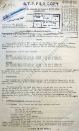
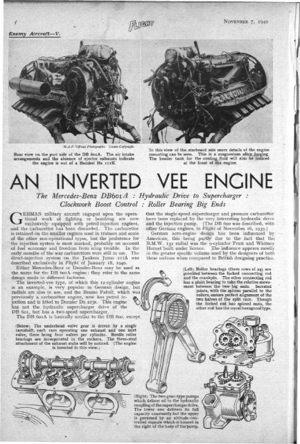
NOVEMBER 7, 1940Enemy<strong>Aircraft</strong>—V.M.A.POfficial Photographs.Rear view on the port side of the DB 601A. The air intakearrangements and the absence of ejector exhausts indicatethe engine is out of a Heinkel He 111K.In this view of the starboard side more details of the enginemounting can be seen. This is a magnesium alloy lorging.The header tank for the cooling fluid will also be noticedat the front of the engine.ANINVERTED VEE ENGINEThe Mercedes-Benz DB601A : Hydraulic Drive to Supercharger :Clockwork Boost Control : Roller Bearing Big EndsGERMAN military aircraft engaged upon the operationalwork of fighting or bombing are nowexclusively equipped with petrol-injection engines,and the carburettor has been discarded. The carburettoris retained on the smaller engines used in trainers and someof the other non-operational types, but the preference forthe injection system is most marked, probably on accountof fuel economy and freedom from icing trouble. In theearly months of the war carburettors were still in use. Thedirect-injection system on the Junkers Jumo 21 iA wasdescribed exclusively in Flight of January 18, 1940.Either Mercedes-Benz or Daimler-Benz may be used asthe name for the DB 601A engine ; they refer to the samedesign made in different factories.The inverted-vee type, of which this 12-cylinder engineis an example, is very popular in German design, butradials are also in use, and the Bramo Fafnir, which waspreviously a carburettor engine, now has petrol injectionand is fitted to Dornier Do 215s. This enginehas not the hydraulic supercharger drive of theDB 601, but has a two-speed supercharger.The DB 601A is basically similar to the DB 600, except(Below) The underhead valve gear is driven by a singlecamshaft, each cam operating one exhaust and one inletvalve, there being four valves per cylinder. Needle rollerbearings are incorporated in the rockers. The three-studattachment of the exhaust stubs will be noticed. (The engineis inverted in this view.)that the single-speed supercharger and pressure carburettorhave been replaced by the very interesting hydraulic driveand the injection pump. (The DB 600 was described, withother German engines, in Flight of November 16, 1939.)German aero-engine design has been influenced byAmerican, this being partly due to the fact that the.B.M.W. 132 radial was the g-cylinder Pratt and WhitneyHornet built under licence. The influence appears mostlyin the greater specific volume used by the designers of boththese nations when compared to British designing practice.(Left) Roller bearings (three rows of 24) areprovided between the forked connecting rodand the crankpin. The other connecting rodhas a plain bearing to take the relative movementbetween the two big ends. Serratedjoints, with the splines parallel to therollers, ensure perfect alignment of thetwo halves of the split race. Thoughthe forked rod has splined nuts, theother rod has the usual hexagonal type.(Right) The two gear-type pumpswhich deliver oil to the hydrauliccoupling of the supercharger drive.The lower one delivers its fullcapacity constantly but the upperis governed by an altitude-controlledcapsule which is housed inthe right of the body of the pump.
NOVEMBER 7, 1940A comparison of the take-off power of our Rolls-RoyceMerlin X with its capacity of 27 litres against that of theDB 601A with the considerably larger capacity of 33.9litres is revealing. The Merlin rating gives 1,065 h.p. forthree minutes at 5! lb. /sq. in. boost and 3,000 r.p.m. TheDB 601A rating is very similar, being 1,050 h.p. for oneminute with a boost of 5.2 lb./sq. in. at 2,400 r.p.m. Thedifference in capacity is, of course, most marked.Hydraulic CouplingWhat is undoubtedly the most interesting feature—it isbelieved to be unique—is the fluid drive to the supercharger.This hydraulic coupling operates on the principleof the '' fluid flywheel'' well known in automobile engineering.Under this system power is transmitted fromdriving to driven member by the continuous circulation ofoil in the curved channels of both members.In the drive of the DB 601 A, oil is pumped along apassage A in the shaft of the driving member (the otherend of which runs in a spigot bearing) and then emergesthrough the radial holes of the shaft B into the radialpassages C of this member. The rotation causes it to flowoutwards, and the shape of the passages is such that theoil is directed into the similar passages D of the drivenmember. As it has a component of tangential velocity itimpinges on the vanes and so drives the member round.The fluid, in going from driving to driven member, mustcross the small gap between them, and a certain loss offluid occurs continuously. Hence the need for pumpingthe oil into the coupling. Slip between driving and drivenmembers is always a characteristic of hydraulic couplings,but this decreases with increase of speed and is also affectedby the amount of oil in the passages of the coupling.It is this last characteristic which is turned to goodaccount in the adoption of the coupling tosupercharger drive. At the "superchargealtitude" of the engine a "solid" drive is required,and the coupling will give this if theoil passages are keptfilled. (This must bequalified by sayingthat hydraulic drive isnever quite "solid,"the minimum of slipnever being lower than2 or 3 per cent.)Below the superchargeheight it isdesired to run thesupercharger at lower/ •The supercharger of the DB 600 will be seen inthis drawing. The DB 600 was the forerunnerof the DB 601A and has the same dimensions,but lacked the hydraulic coupling.(Left) The "dry " cylinder liner is attached tothe cylinder block by a screwed j oint. At its otherend the liner is retained in the crankcase by aring nut which is tightened by means of one ortwo of the tools shown. When rotated in the holesin the crankcase, the pinion of the tool engageswith the gearing on the ring nut.(Below) The Mercedes-Benz DB 601 A inverted veetwelveengine is seen here in the upside down positionduring maintenance work at an Air Ministry stationprior to testing. The bank of injection pumps, thevalve gear and the supercharger will be noticed
NOVEMBER 7, 1940A N I N V E R T E D V E E E N G I N E ( C O N T I N U E Dspeeds in relation to the engine,and this is accomplished by reducingthe oil supply to the coupling.A two-stage pump supplies thecoupling from the main pressureoil filter, each pump stage being ofthe normal gear design. The firststage has no control on it and suppliesthe whole of its output to thecoupling, so that there is alwayssome oil present in the spaces. Theoutput of the second stage isgoverned by a capsule whichresponds to intake pressure, socontrolling a piston valve whichdivides the oil between thecoupling and the by-pass back tothe engine sump. The second stagecommences delivery to the couplingat a barometric height of 4,900ft.,and full delivery occurs at 11,500ft.approximately. In this way is thedesired result of a variable-speeddrive between engine and superchargerobtained.On the Mercedes-Benz thehydraulic coupling is a double-sidedone, the driving member being onthe inside with one driven member on each end. Endthrust is thereby balanced. The inner parts of thehydraulic coupling are light-alloy die-castings. Theannular rings of curved section, which are attached to thetadial vanes and so help to form the correct shape for thefluid channels, are not part of the die-casting. They areseparately made and pinned to the vanes, this form of constructionsimplifying the die-casting considerably.The clearance between the inner driving unit and the(Right) The front view ofthe DB 601A shows thesplined flange for the attachmentof the airscrew hub,and the horseshoe-shapedheader tank under the cowling.The air intake is onthe right.(Below) The hydrauliccoupling driving the supercharger.Oil is supplied toit through the hole A andthen passes out of the shaftB through small holes to thecurved passages C of thedriving member. By centrifugalaction it is flung intothe passages of the drivenmember D and so causes itto rotate. The arrangementis duplicated on the otherend, so balancing end thrust.M.A .P. Official Pholo. Crown Copyright.M .A .P.Official Photo.Crown -CopyrightView of the underside of a damagedMercedes-Benz DB 601A. The injectionpumps lie in between thetwo banks of cylinders.outer driven casing is very close.The slots on the inner unit probablyserve to aid lubrication. Thedriven casing is of steel, ribbed onthe outside to give strength withlightness.A capsule-controlled butterflythrottle controls the superchargerdelivery, and a second throttle,operated by the pilot, controls theair supply to the engine, and thereforethe induction manifoldpressure. The capsule controllingthe first throttle is subjected to thepressure between the two throttles.Worthy of note is the clockworkmechanism which permits theboost to be increased for oneminute only at take-off. TheGerman boost gauge is marked,not in kilogrammes per squaremm. or millimetres of mercury, butin tenths of an atmosphere. Thedial shows from 0.6 to 1.8, which limits are much widerthan those which can be reached. It has been reportedthat the Mercedes-Benz has run up to 1.45 atmospheres( + 6.3 lb./sq. in.) and 2,500 r.p.m. for take-off, but thisseems very high and the claim has not been substantiated.The highest figure seen on a machine by Air Ministrytechnicians was 1.4 atmospheres ( + 5.6 lb./sq. in.) on aHeinkel He 111K.The supercharger is mounted neatly on the port side ofthe engine, with its axis atfight angles to the crankshaft.This necessitatesbevel gearing for the drive(which has a ratio of 10.39to 1) but allows the air intaketo be. of neat designwith merely one right-angleturn, well louvred to minimiseeddy loss.Big-end RollerBearingsThe big-end bearing ofthe connecting rod showsconsiderable enterprise indesign, roller bearings havingbeen used. This hasthree tracks of 24 rollerseach, running on the crankpin4 and in steel split outerraces, with a split lightalloy cage. Serrated jointsare used as shown in thedrawing. At each of thecrankpins there is one forked rod runningon the roller race, while the other is aplain rod running on a lead-bronze bearingoutside the race. In the small endbronze bushes are fitted. <strong>An</strong> unusualtype of nut is used on the forked rod.Instead of having hexagonal flats, thenut is of circular form with numeroussplines. The first explanation that thiswas for ease in tightening up the nut bysmall amounts does not seem to be thecorrect one, as hexagonal nuts are usedon the bolts of the other rod. Lubrication
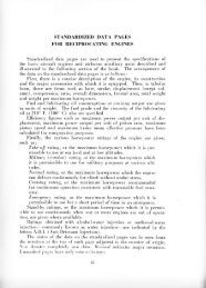
NOVEMBER 7, 1940A N I N V E R T E D V E E E N G I N E ( C O N T I N U E D )of the big end is by forced feed .to the roller bearings andthen out to the plain bearing.Cylinder LinersThe cylinder liners are of the "dry" type made ofsteel. By their tension they hold the surrounding lightalloy cylinder blocks into the crankcase. The attachmentto the crankcase is made by a screwed joint with a largering nut. On the outside of this are cut gear teeth whichengage with the tool used to screw up the nut. Thismight be described as a screwdriver with a small gearpinion instead of a blade. A spigot on the end of this toolis inserted into a hole in the casting and the tool rotated.This turns the ring nut and so tightens it. Considerablemechanical advantage is available for tightening, and twosuch tools can be used simultaneously if required. Thecrankcase is a light-alloy casting with well designed reinforcingwebs. The thin light-alloy top is dowelled andsecured by numerous small studs.The above arrangement of cylinder liner is different fromthat adopted in the Rolls-Royce Merlin, which employs"wet" liners and does not utilise the liner as a meansof attachment for holding cylinder block and crankcasetogether. Instead, a number of long steel bolts performthis function. The Merlin design seems superior, and theprovision of an easier path along which heat may flowfrom the cylinder through the "wet" liner no doubt ispart of the reason why specific power output is higher.Unlike British designs, these Daimler-Benz engines arewater-cooled. Glycol is used in the cooling fluid in theproportion of 30 per cent. Glycol, 70 per cent, water forbombers, and 50-50 for fighters, but the operating temperaturehas not been raised because of this. The additionof Glycol appears to be for anti-freeze purposes onlyTo each block of cylinders there is only one camshaft.Each cam operates two valves, an inlet and an exhaust.There are two inlet and two exhaust valves to each cylinder.Between the stud on the rocker arm and the end ofthe tappet is a floating spherical joint. Rocker arms haveneedle roller bearings, and tappet adjustments are mostaccessible. The whole valve gear is very well arranged.A Bosch magneto is fitted to the DB 601A, this beinga twin ignition unit with two electrical circuits but only onedrive from the engine, so not true " dual ignition." This isnot universal German practice.Injection PumpsBefore going to the injection pumps the petrol goesthrough the de-aerator, which is interposed between thefuel pump and the injection pump. The injection pumpsare of Bosch type, the twelve being arranged neatly inline in four groups of three. They operate in exactly thesame way as the Junkers pump on the Jumo 211A, butthey are mounted in a more accessible manner.The injectors on the DB 601A differ from the Junkerstype, which is simply a nozzle designed to admit thecharge to the cylinder in a finely divided state. But thetype which Mercedes-Benz fit is not only a nozzle but isspring-loaded to act also as a valve.All German engines for military operation have beenfound to contain 92 octane leaded fuel in the tanks. Thisgrade of fuel is used for take-off and all other conditionsof flight. But the DB 601A was designed for 87 octane,so higher-grade fuel is apparently not yet short.The German method of attaching the airscrew to theengine differs from the parallel splining of the shaft used asstandard in this country. Their method adopts flangemountingin preference to shaft-mounting, and carries thedrive to the airscrew nub by two plates bolted together, theload being carried through radial serrations on the facesof the plates.A large number of German engines have been capturedand are available for test and experiment in the enginelaboratories of the Air Ministry. Some of them have hadvery few operational flying hours, even as low as underten. <strong>An</strong>d many are of recent date of manufacture, thename plate of one out of a Messerschmitt Me 109 indicatingthat it was made in the first half of this year.The standard of workmanship seen on the details ofthe Mercedes-Benz engines which have been captured canonly be described as excellent. Also the arrangement ofpiping is very neat and some thought has been expendedon the placing of accessories. But whether this has beenentirely successful is doubtful, for as one observer describedit, they appeared to be "regimented." Mercedes-Benz design is not so heavy in appearance as Junkers.The designers appear to have gone in for simplicity ofappearance, sometimes at the cost of the general excellenceof the engine. They do not seem to have equalled Rolls-Royce and Bristol in the finesse and artistry of design.Power-Weight RatioThe particular engine inspected had not been powertestedon the brake, but it was expected to give withinabout 40 h.p. of the rated powers. Using the take-offrating of 1,050 h.p. and the weight of 1,610 lb., the powerweightratio is 1.53 lb./h.p.The take-off power of 1,050 h.p. is lower than the figurewhich has been accepted previously and which Flight haspublished as 1,150 h.p. But after careful examination, AirMinistry technicians state that they can find no evidence ofthe engine being used at take-off powers higher than this.Other data on the engine are:CONTROL : Single throttle control from pilot's cockpit.BORE AND STROKE : 150 mm. x 160 mm.STROKE VOLUME: 33.9 litres.COMPRESSION RATIO: 6.9/1.REDUCTION GEAR: Spur type, 14/9-THRUST BEARING : Normal ball type.WIDTH: 29.1m. LENGTH: 67.5111. HEIGHT: 40.5m.WEIGHT: Oily, with fuel pump, generator, hydraulic pump, starter,airscrew control gear, piping and wiring to bulkhead; 1,610 Ib.CRANKSHAFT: One-piece type, with six cranks at 120 deg. and eightbalance weights each consisting of two plates riveted on each sideof a crankweb extension. Runs in seven lead-bronze bearings.Front end splined to take splined mounting sleeve of reductiongear pinion. Rear end fitted with starter dog and accessory drive.BIG-END BEARING : Roller type with three tracks of 24 rollers each,running on crankpins and in steel split outer races, with splitlight-alloy cage, with serrated joints.PISTONS: Light alloy of normal design, floating gudgeon pin. Threecompression rings and two scraper rings.VALVE GEAR : Bevel drive to camshafts. Single underhead shalt oneach block, with one cam operating one inlet and exhaust valve,through rocker arms with needle roller bearings.VALVES : Hollow stem, exhaust valve sodium cooled.SPARKING PLUGS : Two per cylinder, fitted on outside of block.INJECTION PUMP: Bosch twelve-cylinder in-line type, fitted betweencylinder blocks, and controlled by induction manifold pressuresensitive diaphragm, altitude pressure sensitive capsule stack, andinduction temperature sensitive capsule. De-aerator interposedbetween fuel pump and injection pump.MAGNETO: Bosch twin unit, Z.M.12 B.R.4 type.AUXILIARIES: Mounted on gear box at rear end; gear-type fuelpump, 24-volt, 1,500-watt generator, swashplate driven six-plungerhydraulic pump (alternatively, vacuum pump), centrifugal coolantpump, and hand/electric inertia starter.On. PUMPS : Gear-type pressure pump delivering through wire-woundfilter. The main oil supply is led by drilled crankcase passagesto the main bearings. Scavenge oil drains from front and rearto the camcase covers, in each ct which is a gear-type pump.POWER: Take-off, 1,050 b.h.p. at 5.2 lb./sq. in. boost and 2,400r.p.m. (limited by clockwork to 1 min.).For 5 min., at ground level, 950 b.h.p. at 3.75 lb./sq. in. and2,400 r.p.m.Power at altitude, 970 b.h.p. at 2.4 lb./sq. in. and 2,300 r.p.m.at 12,000ft.OIL COOLER : The cooler area is increased by 50 per cent, in orderto dissipate the energy not transmitted by the superchargerhydraulic coupling at maximum slip.EXHAUSTS : Ejector-type exhaust stubs are fitted when the engineis installed in the Me 109.