Crown Boiler Series 24 Commercial Boilers - LSKair
Crown Boiler Series 24 Commercial Boilers - LSKair
Crown Boiler Series 24 Commercial Boilers - LSKair
- No tags were found...

You also want an ePaper? Increase the reach of your titles
YUMPU automatically turns print PDFs into web optimized ePapers that Google loves.
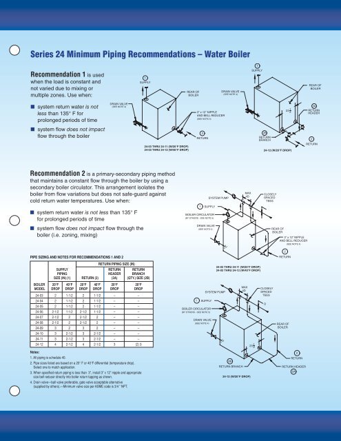
<strong>Series</strong> <strong>24</strong> Minimum Piping Recommendations – Water <strong>Boiler</strong>1Recommendation 1 is usedwhen the load is constant andnot varied due to mixing ormultiple zones. Use when:1SUPPLYREAR OFBOILERDRAIN VALVE(SEE NOTE 4)SUPPLYREAR OFBOILER■ system return water is notless than 135° F forprolonged periods of time■ system flow does not impactflow through the boilerDRAIN VALVE(SEE NOTE 4)3” x 12” NIPPLEAND BELL REDUCER(SEE NOTE 3)2RETURN<strong>24</strong>-03 THRU <strong>24</strong>-11 (W/20°F DROP)<strong>24</strong>-03 THRU <strong>24</strong>-12 (W/40°F DROP) <strong>24</strong>-12 (W/20°F DROP)23 212ARETURNHEADER2BRETURNBRANCH 2RETURNRecommendation 2 is a primary-secondary piping methodthat maintains a constant flow through the boiler by using asecondary boiler circulator. This arrangement isolates theboiler from flow variations but does not safe-guard againstcold return water temperatures. Use when:■ system return water is not less than 135° Ffor prolonged periods of timeSYSTEM PUMP1 SUPPLYBOILER CIRCULATOR(BY OTHERS - SEE NOTE 5)MAX4DCLOSELYSPACEDTEESBOILER CIRCULATOR(BY OTHERS - SEE NOTE 5)DRAIN VALVE(SEE NOTE 4)SYSTEM PUMPSUPPLY■ system flow does not impact flow through theboiler (i.e. zoning, mixing)DRAIN VALVE(SEE NOTE 4)REAR OFBOILER3” x 12” NIPPLEAND BELL REDUCER(SEE NOTE 4)PIPE SIZING AND NOTES FOR RECOMMENDATIONS 1 AND 2RETURN PIPING SIZE (IN)SUPPLY RETURN RETURNPIPING HEADER BRANCHSIZE (IN) (1) RETURN (2) (2A) (QTY.) SIZE (2B)BOILER 20°F 40°F 20°F 40°F 20°F 20°FMAXMODEL DROP DROP DROP DROP DROP DROP4DSYSTEM PUMP<strong>24</strong>-03 2 1-1/2 2 1-1/2 – –MAX<strong>24</strong>-04 2 1-1/2 2 1-1/2 – CLOSELYSUPPLY4D –SYSTEM PUMPSPACED<strong>24</strong>-05 2 1-1/2 2 1-1/2 – – TEESBOILER CIRCULATOR<strong>24</strong>-06 2-1/2 1-1/2 2-1/21SUPPLY 1-1/2 – –(BY OTHERS - SEE NOTE 5)<strong>24</strong>-07 2-1/2 2 2-1/2 2 – –<strong>24</strong>-08 2-1/2BOILER CIRCULATORDRAIN VALVE(BY 2 OTHERS 2-1/2 - SEE NOTE 5) 2 – –(SEE NOTE 4)<strong>24</strong>-09 3 2 3 2 – –<strong>24</strong>-10 3 2-1/2DRAIN VALVE(SEE3NOTE2-1/<strong>24</strong>)– –REAR OF<strong>24</strong>-11 3 2-1/2 3 2-1/2 – –BOILER3” x 12” NIPPLE<strong>24</strong>-12 4 2-1/2 4 2-1/2 3 (2) 3AND BELL REDUCER2312(SEE NOTE 4)Notes:1. All piping is schedule 40.22. Pipe sizes listed are based on a 20° F or 40°F differential (temperature drop).RETURN2BSelect one to match application.RETURN BRANCH3. When specified return piping is less than 3”, install <strong>24</strong>-03 3” x 12” THRU nipple <strong>24</strong>-11 and (W/20°F appropriate DROP)size bell reducer directly into boiler return tapping as <strong>24</strong>-03 shown. THRU <strong>24</strong>-12 (W/40°F DROP) <strong>24</strong>-12 (W/20°F DROP)4. Drain valve—ball valve preferable, gate valve acceptable alternative(supplied by others).—Minimum valve size per ASME code is 3/4 ” NPT.CLOSELYSPACEDTEESD2RETURNREAR OFBOILER2RETURNRETURN HEADER2ARETU<strong>24</strong>-03 THRU <strong>24</strong>-11 (W/20°F DROP)<strong>24</strong>-03 THRU <strong>24</strong>-12 (W/40°F DROP) <strong>24</strong>