A Small Yagi for 50 MHz - ONZ.be
A Small Yagi for 50 MHz - ONZ.be
A Small Yagi for 50 MHz - ONZ.be
- No tags were found...

Create successful ePaper yourself
Turn your PDF publications into a flip-book with our unique Google optimized e-Paper software.
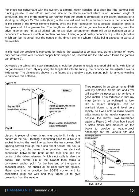
For those not conversant with the system, a gamma match consists of a short bar (the gamma bar)running parallel to and offset from one side of the driven element which is an unbroken length ofconductor. The end of the gamma bar furthest from the boom is connected to the driven element by ashorting bar (Figure 2). The outer (braid) of the coaxial feed line from the transceiver is then connectedto the centre of the driven element boom), while the inner conductor, via a suitable capacitor, goes tothe open end of the gamma bar. The length and diameter of the gamma bar and its spacing from thedriven element are not at all critical, but <strong>for</strong> any given arrangement there will <strong>be</strong> an optimum value ofcapacitor to achieve a match. A problem has <strong>be</strong>en finding a good quality capacitor of just the right valuewhich can <strong>be</strong> mounted near the centre of the driven element where it risks <strong>be</strong>ing exposed to worst ofthe weather.In this yagi the problem is overcome by making the capacitor a coaxial one, using a length of heavyduty coaxial cable with its outer copper braid stripped off, inserted into the tu<strong>be</strong> which <strong>for</strong>ms the gammabar. (Figure 2).Obviously the tubing and coax dimensions should <strong>be</strong> chosen to result in a good sliding fit, with little orno gap <strong>be</strong>tween them. By adjusting the length slid into the tubing, the capacity can <strong>be</strong> adjusted over awide range. The dimensions shown in the figures are probably a good starting point <strong>for</strong> anyone wantingto duplicate this antenna.Figure 3pieces. A piece of sheet brass was cut to fit inside thebottom of the box , <strong>for</strong>ming a mounting plate <strong>for</strong> a SO 239socket bringing the feed line up from the transceiver. Selftapping screws through the brass sheet secure the box tothe boom , at the same time providing an electricalconnection <strong>be</strong>tween the braid of the feed line and thecentre of the driven element (which electrically is also theboom). The centre pin of the SO239 then <strong>for</strong>ms aconvenient anchor point <strong>for</strong> the free end of the gammacapacitor cable. This should all <strong>be</strong> clear from the figures.Make sure that in practice the SO239 socket and itsassociated plug are well and truly taped up to giveprotection from the weather.They resulted in an almost unity SWRwith my antenna. Some trial and errorwill usually <strong>be</strong> necessary to achieve agood match. I am <strong>for</strong>tunate in that mymast (which is camouflaged to looklike a square drainpipe) can <strong>be</strong>cranked down to ground level veryrapidly, so I was able to make severaladjustments to the tubular capacitor toachieve the lowest SWR.Referenceagain to Figure 2 will show how I useda small plastic box mounted on theboom to provide a weatherproofanchorage <strong>for</strong> the various bits andFIGURE 4[ HAMMAG N.12 January 2010 ]