General Purpose Three-Phase Induction Motors ... - Cantoni Group
General Purpose Three-Phase Induction Motors ... - Cantoni Group
General Purpose Three-Phase Induction Motors ... - Cantoni Group
- No tags were found...

You also want an ePaper? Increase the reach of your titles
YUMPU automatically turns print PDFs into web optimized ePapers that Google loves.
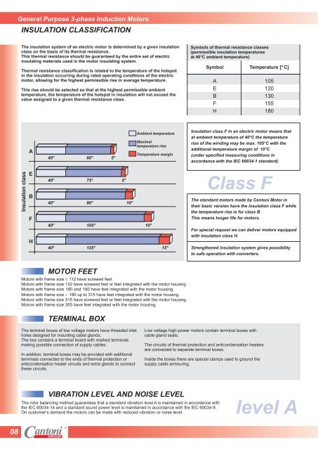
<strong>General</strong> <strong>Purpose</strong> 3-phase <strong>Induction</strong> <strong>Motors</strong>INSULATION CLASSIFICATIONThe insulation system of an electric motor is determined by a given insulationclass on the basis of its thermal resistance.This thermal resistance should be guaranteed by the entire set of electricinsulating materials used in the motor insulating system.Thermal resistance classification is related to the temperature of the hotspotin the insulation occurring during rated operating conditions of the electricmotor, allowing for the highest permissible rise in average temperature.This rise should be selected so that at the highest permissible ambienttemperature, the temperature of the hotspot in insulation will not exceed thevalue assigned to a given thermal resistance class.Symbols of thermal resistance classes(permissible insulation temperaturesat 40°C ambient temperature)Symbol Temperature [° C]A 105E 120B 130F 155H 180A40°60°5°Ambient temperatureMaximaltemperature riseTemperature marginInsulation class F in an electric motor means thatat ambient temperature of 40°C the temperaturerise of the winding may be max. 105°C with theadditional temperature margin of 10°C(under specified measuring conditions inaccordance with the IEC 60034-1 standard).Insulation classEBFH40°40°40°40°75°80°105°125°5°10°10°15°Class FThe standard motors made by <strong>Cantoni</strong> Motor intheir basic version have the insulation class F whilethe temperature rise is for class B.This means longer life for motors.For special request we can deliver motors equippedwith insulation class H.Strengthened insulation system gives possibilityto safe operation with converters.MOTOR FEET<strong>Motors</strong> with frame size 112 have screwed feet.<strong>Motors</strong> with frame size 132 have screwed feet or feet integrated with the motor housing.<strong>Motors</strong> with frame size160 and180 have feet integrated with the motor housing.<strong>Motors</strong> with frame size 180 up to 315 have feet integrated with the motor housing.<strong>Motors</strong> with frame size 315 have screwed feet or feet integrated with the motor housing.<strong>Motors</strong> with frame size 355 have feet integrated with the motor housing.TERMINAL BOXThe terminal boxes of low voltage motors have threaded inletholes designed for mounting cable glands.The box contains a terminal board with marked terminalsmaking possible connection of supply cables.In addition, terminal boxes may be provided with additionalterminals connected to the ends of thermal protection oranticondensation heater circuits and extra glands to connectthese circuits.Low voltage high-power motors contain terminal boxes withcable gland seals.The circuits of thermal protection and anticondensation heatersare connected to separate terminal boxes.Inside the boxes there are special clamps used to ground thesupply cable armouring.VIBRATION LEVEL AND NOISE LEVELThe rotor balancing method guarantees that a standard vibration level A is maintained in accordance withthe IEC 60034-14 and a standard sound power level is maintained in accordance with the IEC 60034-9.On customer’s demand the motors can be made with reduced vibration or noise level.level A08