Cylinder-Head Bolts - Elring
Cylinder-Head Bolts - Elring
Cylinder-Head Bolts - Elring

Create successful ePaper yourself
Turn your PDF publications into a flip-book with our unique Google optimized e-Paper software.
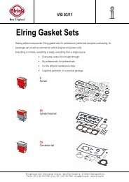
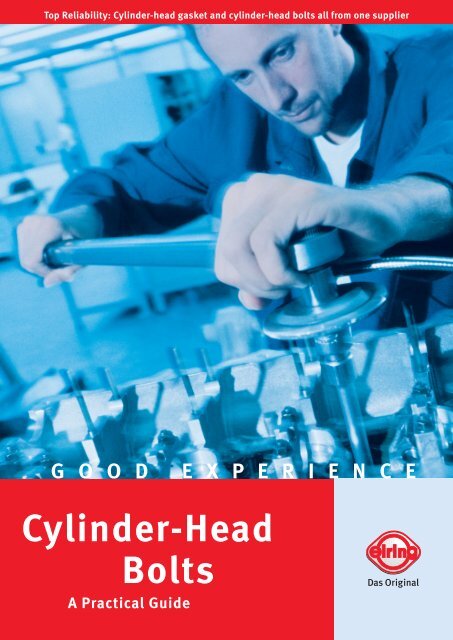
Top Reliability: <strong>Cylinder</strong>-head gasket and cylinder-head bolts all from one supplier<br />
G O O D E X P E R I E N C E<br />
<strong>Cylinder</strong>-<strong>Head</strong><br />
<strong>Bolts</strong><br />
A Practical Guide
2<br />
Reliability is not a flexible term<br />
The right turn for optimal reliability
<strong>Elring</strong> – even better service.<br />
For the current generation of engines, the profes-<br />
sional repairing of the cylinder head sealing<br />
system requires that both components – cylinder-<br />
head gasket and cylinder-head bolts – be re-<br />
placed with new parts.<br />
With the new full range of cylinder-head bolts<br />
from <strong>Elring</strong>, you save time and money. Because<br />
now everything is available from one supplier:<br />
the cylinder-head gasket and the matching cylin-<br />
der-head bolt set<br />
• for practically all cars and commercial vehicles<br />
(see <strong>Cylinder</strong>-<strong>Head</strong> Bolt catalogue)<br />
• of tested quality<br />
• assortments selected individually for each<br />
engine repair<br />
• packed in a special box with thread protection<br />
• practical and fast<br />
• direct from the gasket manufacturer<br />
<strong>Cylinder</strong>-head bolts<br />
<strong>Cylinder</strong>-head gasket<br />
<strong>Elring</strong> cylinder-head bolts are available for:<br />
Alfa Romeo I Audi I BMW I Citroën I Daewoo I Deutz I<br />
Fiat I Ford I Honda I Hyundai I Isuzu I Iveco I<br />
Kia I Lada I Land Rover I Lancia I MAN I Mazda I<br />
Mercedes-Benz (cars and commercial vehicles) I<br />
Mitsubishi I Nissan I Opel I Peugeot I Renault I<br />
Rover I Saab I Scania I Seat I Sˇkoda I Ssangyong I<br />
Suzuki I Talbot I Toyota I Vauxhall I Volkswagen I<br />
Volvo (cars and commercial vehicles)<br />
<strong>Cylinder</strong>-head repair<br />
Contents: <strong>Cylinder</strong>-<strong>Head</strong> <strong>Bolts</strong> – A Practical Guide<br />
1. <strong>Cylinder</strong> head bolting Page 4<br />
2. How they work Page 6<br />
3. Types of bolts Page 8<br />
4. Tightening procedure Page 10<br />
5. Professional repairs Page 13<br />
6. Testing the quality Page 14<br />
7. Technical details Page 16<br />
8. Packaging Page 17<br />
Absolutely reliable<br />
seal and<br />
top engine performance<br />
3
4<br />
1. <strong>Cylinder</strong> head bolting<br />
Fascinating reliability.<br />
<strong>Cylinder</strong> head bolting without the need for<br />
retightening is standard for modern engine<br />
design. There are technical and economic<br />
reasons for this, both when manufacturing<br />
and repairing engines:<br />
• uniformly high clamp force on all bolts<br />
• reliable, functioning sealing system<br />
• cost savings<br />
To ensure reliable cylinder head bolting while<br />
at the same time no need for retightening,<br />
all parts involved in the cylinder head sealing<br />
system must be finely tuned to each other<br />
already in the developmental stage.<br />
Both the design and the material quality of<br />
the cylinder-head bolt contribute significantly<br />
to the reliability of the sealing system.<br />
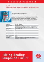
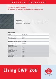
Tensile and compression stress<br />
in the cylinder-head sealing system –<br />
visualized using the Finite Element<br />
Method
The cylinder head<br />
sealing system<br />
<strong>Cylinder</strong>-head bolts<br />
<strong>Cylinder</strong> head<br />
<strong>Cylinder</strong>-head gasket<br />
Crankcase<br />
Liner (depending on<br />
the engine design)<br />
5
6<br />
2. How they work
Effective forces.<br />
<strong>Cylinder</strong>-head bolts are the design elements<br />
of the cylinder head sealing system that generate<br />
the required surface pressure, transmitting it<br />
to the engine components. This requires that the<br />
cylinder-head bolts be tightened in close com-<br />
pliance with the specified instructions and in the<br />
specified sequence (see section 4).<br />
Only the total force available to the cylinder-head<br />
gasket can be distributed by the gasket to<br />
the various areas to be sealed (gas, water and oil<br />
seal). We refer to this as the specific sealing<br />
compression distribution.<br />
Therefore:<br />
The overall clamp force generated by the cylinder-<br />
head bolts and its uniform distribution across<br />
the entire sealing system is a major prerequisite<br />
for the function of the cylinder-head gasket.<br />
Modern lightweight engine designs have de-<br />
manding requirements, such as<br />
• higher ignition pressures (up to 220 bar)<br />
• increasing relative motion of the engine<br />
components<br />
• decreasing engine rigidity and greater thermal<br />
component elongation due to the aluminum/<br />
magnesium construction<br />
• reduction of distortion of cylinder bores and<br />
cylinder head (keyword: reduced bolt forces).<br />
In order to meet these requirements, the<br />
cylinder-head bolt has also undergone signifi-<br />
cant changes in the last several decades of<br />
engine engineering. Its properties must fulfill<br />
the specific requirements of the engine in detail.<br />
In addition to the improved materials and<br />
manufacturing processes for the bolts, the most<br />
significant modifications have been made<br />
• in the bolt design (see section 3)<br />
and<br />
• in the tightening procedure (see section 4).<br />
The surface coatings of the bolts have also been<br />
modified to provide more favorable friction<br />
conditions.<br />
7
8<br />
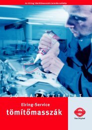
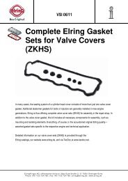
3. Types of bolts<br />
a) Thread rolling bolts with<br />
short thread<br />
b) Thread rolling bolt with<br />
long thread<br />
c) Helix bolt d) Anti-fatigue shaft bolt<br />
The new types of cylinder-head<br />
bolts: first choice for lightweight<br />
engines.<br />
The thermal expansion of lightweight engine<br />
designs such as<br />
• aluminum cylinder head and gray cast iron<br />
crankcase<br />
• cylinder head and crankcase of aluminum<br />
is different than that of the steel cylinder-head<br />
bolt. The thermal expansion of the aluminum<br />
engine components is roughly twice that of the<br />
cylinder-head bolts.
The use of lightweight materials for engine parts<br />
and the modified tightening procedure (see<br />
section 4) are the reasons why primarily the fol-<br />
lowing bolt designs are used for cylinder head<br />
bolting on modern engine designs.<br />
Thread rolling bolts.<br />
Used mainly for car engines. Thread rolling bolts<br />
have a rolled thread on the shaft. The bolt<br />
then does not require machining. The elasticity<br />
properties of the thread rolling bolt with long<br />
thread are very similar to those of the anti-<br />
fatigue shaft bolt, which requires machining.<br />
That is why this is referred to as an inexpensive<br />
type of anti-fatigue shaft bolt.<br />
a) Thread rolling bolts with short thread.<br />
The thread is rolled onto these bolts only up<br />
to the maximum length of thread engagement.<br />
The top turn takes on the greatest amount of<br />
force and therefore usually undergoes a perma-<br />
nent plastic deformation.<br />
b) Thread rolling bolts with long thread.<br />
These bolts have a very long threaded section<br />
that usually extends to just under the bolt<br />
head. This is where the elastic and plastic elon-<br />
gation of the bolt occurs during tightening<br />
and when the engine is in operation. The design<br />
with the long thread increases the elasticity, pro-<br />
vides uniform tension along the shaft and<br />
gives the bolt sufficient capacity for plastic defor-<br />
mation, ensuring the durability of the entire<br />
cylinder head sealing system.<br />
c) Helix bolts.<br />
Helix bolts are bolts onto which a coarse single<br />
or multiple thread is rolled as a helix. The<br />
helix increases the elasticity on this bolt also,<br />
ensuring a uniform distribution of tension.<br />
The elastic resilience of the helix bolt depends<br />
on the core diameter of the selected helix<br />
profile – the smaller the diameter, the more simi-<br />
lar the bolt characteristics are to an anti-<br />
fatigue shaft bolt.<br />
d) Anti-fatigue shaft bolts.<br />
This bolt design is often used for engines on<br />
commercial vehicles and is characterized by a<br />
tapered shaft extending from the thread to just<br />
below the bolt head. Because of the smaller<br />
cross section compared to the full shaft bolts,<br />
greater elastic and plastic resilience is achieved.<br />
The plastic elongation that is important for<br />
repairs occurs in the tapered shaft section of the<br />
bolt without thread engagement.<br />
9
10<br />
Bolt force<br />
F [in kN]<br />
Tightened only<br />
with torque<br />
4. Tightening procedure<br />
Elastic<br />
range<br />
Elastic tightening of bolts<br />
Taking a turn for more reliability.<br />
In collaboration with engine manufacturers and<br />
the supplier industry, extensive testing and<br />
development programs have been carried out to<br />
significantly improve sealing joints with better<br />
engine components and techniques such as<br />
• ˝Metaloflex ® ˝ cylinder-head gaskets with<br />
high compression potential and low settling<br />
behavior<br />
• cylinder-head bolts with special plastic defor-<br />
mation characteristics (see section 3)<br />
• new tightening procedure for cylinder-head<br />
bolts (see section 4.2 and 4.3)<br />
These components ensure a reliable seal, espe-<br />
cially for long-term performance.<br />
Large bolt force scatter<br />
of up to +/– 20 %<br />
Bolt elongation<br />
Δ L [in mm]<br />
MA<br />
FV<br />
FV<br />
MK<br />
MG<br />
Forces and torque values<br />
when tightening<br />
4.1. Tightening of bolts<br />
with torque.<br />
<strong>Cylinder</strong>-head bolts used to be tightened with a<br />
precisely defined torque in several stages<br />
within the elastic elongation range of the bolt<br />
material (chart – bottom left).<br />
Disadvantages of torque-controlled tightening:<br />
1. When applying the tightening torque M A, bolt<br />
force deviations of the clamp force F V of ± 20%<br />
arise due to the different friction torques for<br />
the head (M K) and thread (M G) – see figure at bot-<br />
tom right. It was not possible to achieve a uni-<br />
form distribution of the compression across the<br />
entire sealing system using this procedure.<br />
2. As a result of the cold-static settling processes<br />
of the soft material gasket after installation<br />
(=loss of clamp force) and a further loss of force<br />
when the engine is operating, the bolts<br />
had to be retightened after the engine had run a<br />
specified mileage. But with the retightening<br />
of the cylinder-head bolts, the scatter of the bolt<br />
forces was by no means eliminated.
4.2. Bolt tightening using<br />
torque and rotational angle on the<br />
new generations of engines.<br />
In this process, the cylinder-head bolt undergoes<br />
not only elastic elongation but also plastic<br />
elongation. This provides significant advantages<br />
in comparison to the tightening of bolts with<br />
torque.<br />
Description of the combined procedure.<br />
In the torque/angle-controlled tightening pro-<br />
cess, the bolt is tightened in the first stage<br />
with a defined low torque in the elastic range of<br />
the bolt characteristic curve (chart below).<br />
Bolt force<br />
F [in kN]<br />
Yield point<br />
Elastic<br />
range<br />
1 st step:<br />
Tightening<br />
with torque<br />
Plastic tightening of bolts<br />
Small bolt force<br />
fluctuation<br />
of a few %<br />
Plastic<br />
range<br />
Bolt elongation<br />
2 Δ L [in mm]<br />
nd step:<br />
Tightening<br />
with rotational<br />
angle<br />
Tightening cylinder-head bolts<br />
using rotational angle disc<br />
At the end of the torque-controlled tightening, the<br />
bolt is tightened further by a specified rotation-<br />
al angle. This deforms the bolt material plastically<br />
beyond the yield point (which denotes the<br />
transition from the elastic to the plastic range).<br />
Advantages of the rotational angle tightening:<br />
1. In conjunction with the new bolt designs,<br />
this tightening method can significantly reduce<br />
the fluctuation of the bolt clamp forces.<br />
The application of the rotational angle does not<br />
result in greater clamp force but rather<br />
only in plastic elongation of the bolt, thus ensur-<br />
ing that the bolt force level is consistently<br />
high for all cylinder-head bolts. This is an impor-<br />
tant prerequisite for an overall leak-free<br />
sealing system.<br />
2. It is no longer necessary to retighten the<br />
cylinder-head bolts. This is made possible in part<br />
thanks to the metal-layer gaskets, which settle<br />
only slightly. The remaining bolt force fluctua-<br />
tion can be traced back to the dimensional produc-<br />
tion tolerances for the bolts and strength toler-<br />
ances for the materials.<br />
11
12<br />
4. Tightening procedure<br />
7<br />
8<br />
3<br />
4<br />
1<br />
Start<br />
Tightening sequence for cylinder head (example)<br />
4.3. Tightening sequence.<br />
The cylinder-head bolts (e.g. 1- 10 on a 4 cylin-<br />
der engine, illustrated above) are to be tightened<br />
in a precisely defined sequence (see manufac-<br />
turer’s instructions). Like tightening torque and<br />
tightening angle, this sequence is specified<br />
by the engine and gasket manufacturers and<br />
depends on the individual engine design. Infor-<br />
mation for specific engines in several languages<br />
– for instance tightening instructions – is in-<br />
cluded with each cylinder-head gasket and every<br />
set of gaskets from <strong>Elring</strong>.<br />
2<br />
<strong>Cylinder</strong> 1 <strong>Cylinder</strong> 2 <strong>Cylinder</strong> 3 <strong>Cylinder</strong> 4<br />
6<br />
5<br />
10<br />
9<br />
The bolts are tightened in several steps, for<br />
instance:<br />
•1 st step 20 Nm (i.e. tighten bolts 1 – 10 with<br />
tightening torque of 20 Nm)<br />
•2 nd step 60 Nm (i.e. tighten bolts 1 – 10 with<br />
tightening torque of 60 Nm)<br />
•3 rd step 90° (i.e. tighten bolts 1 – 10 with a<br />
rotational angle of 90°)<br />
•4 th step 90° (i.e. tighten bolts 1 – 10 with a<br />
rotational angle of 90° once again).<br />
Each tightening sequence is based upon the<br />
following rule:<br />
Each bolt tightening procedure always begins in<br />
the middle of the engine (between cylinder 2<br />
and cylinder 3 – see example), moving in a spiral<br />
or crosswise direction outwards along both<br />
sides until the outer bolts on cylinder 1 and cylin-<br />
der 4 have been tightened.<br />
This ensures that the cylinder head and the<br />
cylinder-head gasket is clamped optimally to the<br />
crankcase.<br />
If the specifications are not followed, unde-<br />
sirable irregular tension and distortion of the<br />
engine components can arise.<br />
The consequence: Leaks can occur in the cylin-<br />
der head sealing system.
5. Professional repairs<br />
Only new cylinder-head bolts provide<br />
100% reliability.<br />
The new generations of engines have better<br />
sealing systems finely tuned to the engine<br />
design. And in these systems, the cylinder-head<br />
bolts plays a major role (see section 1 – 4).<br />
<strong>Cylinder</strong>-head bolts can be plastically elongated<br />
by several millimeters over the original state<br />
thanks to<br />
• the new tightening procedure using torque<br />
plus rotational angle (= plastic elongation of<br />
the bolt) as well as<br />
• the modern engine designs, e.g. aluminum-<br />
aluminum pairing (= additional plastic elonga-<br />
tion the first time the engine heats up in<br />
operation).<br />
The elongation of the bolt not only brings about<br />
changes in the strength and elongation proper-<br />
ties of the bolt material but also reduces the bolt<br />
cross section. If this bolt is used again, there<br />
is the danger that the ensuing bolt force can no<br />
longer be sustained by the smaller cross sec-<br />
tion. As a result, the bolt breaks.<br />
Studies have shown that on an M10 bolt of medi-<br />
um strength 10.9, the load capacity can drop<br />
by 10 – 15% with a decrease in diameter of just<br />
0.3 mm. The gasket is then compressed with<br />
insufficient force and can begin to leak in a short<br />
period of time. So for the professional repair-<br />
ing of the cylinder head sealing system, engine<br />
and gasket manufacturers specify the following:<br />
• Use only new cylinder-head bolts and a new<br />
cylinder-head gasket.<br />
• Observe tightening torque and tightening<br />
rotational angle.<br />
• Follow the specified sequence for tightening.<br />
• Make certain that all engine parts are clean and<br />
free of distortion.<br />
• Ensure that the installation is done only by<br />
trained specialists.<br />
• Use high-quality tools.<br />
Plastically elongated<br />
and tapered cylinderhead<br />
bolt<br />
Optimum clamping and a good seal are possible<br />
only if these specifications are followed. <strong>Bolts</strong><br />
that have already been used once and have<br />
undergone plastic elongation may not be used. In<br />
this way, unpleasant consequences such as<br />
leakage and the resulting repair costs, annoyed<br />
customers and image loss can be prevented.<br />
13
14<br />
6. Testing the quality<br />
Bolt test bench – the reliable test to determine the characteristic bolt curve<br />
Tested reliability.<br />
Every engine model places certain demands on<br />
cylinder-head bolts that must be fulfilled to<br />
ensure that the entire sealing system functions<br />
properly.<br />
For that reason, drawings, test reports regarding<br />
initial samples and various chemical and<br />
dimensional protocols for each bolt type are<br />
examined closely.<br />
Before a bolt type is approved, measurements<br />
are taken regularly on a bolt test bench, ensuring<br />
that quality standards are fulfilled.
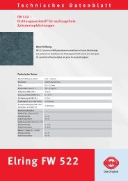
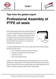
Generation of a characteristic bolt<br />
curve on the bolt test bench.<br />
In the test, the bolt is tightened beyond the level<br />
specified in the tightening procedure (in this<br />
case, torque 60 Nm + rotational angle 180°) to get<br />
a detailed and representative characteristic<br />
bolt curve. The characteristic curve recorded dur-<br />
ing the tightening process is assessed accord-<br />
ing to the following criteria (1 – 4):<br />
1. The bolt force F 1 reached after tightening with<br />
the specified torque and rotational angle (in<br />
this case 60 Nm + 180°) must lie within a defined<br />
force range between the minimum and maxi-<br />
mum force (10 N ~ 1 kg).<br />
4<br />
75000<br />
70000<br />
65000<br />
60000<br />
55000<br />
50000<br />
45000<br />
40000<br />
35000<br />
30000<br />
25000<br />
20000<br />
15000<br />
10000<br />
5000<br />
0<br />
1 2 3 4 5 6 7 8 9 10 11 12 13 14 15 16 17 18 19 20 21 22 23 24 25 26 0<br />
Force [N]<br />
Characteristic<br />
bolt curve<br />
F1<br />
60 Nm + 180°<br />
F max – F1 > 4000 N<br />
F max<br />
Torque[Nm]<br />
Maximum force 400<br />
70500 N<br />
380<br />
360<br />
340<br />
1<br />
320<br />
Plastic<br />
range<br />
Minimum force<br />
300<br />
280<br />
260<br />
2<br />
70 Nm + 900°<br />
Rotational angle up to drop<br />
in force measured starting at<br />
torque = 70 Nm<br />
52000 N<br />
240<br />
220<br />
200<br />
180<br />
160<br />
180°<br />
Characteristic torque curve<br />
140<br />
120<br />
100<br />
80<br />
60<br />
40<br />
20<br />
Elongation after<br />
removal in mm<br />
Angle/60°<br />
Characteristic bolt curve<br />
3<br />
2. After a specific torque (in this case 70 Nm) has<br />
been applied, the bolt must be turned at least<br />
another two rotations ( ± 90° rotational angle, de-<br />
pending on manufacturer). This may not result<br />
in a significant decrease in bolt force.<br />
3. The difference between the measured maxi-<br />
mum force Fmax and the force after tightening F1 must be greater than the value specified by<br />
the manufacturer (in this case 4000 N).<br />
4. The characteristic bolt curve (red-yellow) must<br />
follow the curve depicted here when tightened.<br />
It may not show any leaps or other deviations.<br />
The fulfillment of these four vital criteria on the<br />
bolt test bench as well as the accompanying<br />
dimension and chemical consistency reports en-<br />
sure that the bolt type tested has the potential<br />
to reliably seal the engine.<br />
To round off the chart of the characteristic curve,<br />
the permanent elongation of the bolt after<br />
removal from the test bench is depicted in the<br />
lower left hand corner. When the bolt is loosened,<br />
the characteristic curve moves from the value F1 along the red dotted line downwards. The red<br />
section corresponds to the permanent elongation<br />
of the bolt after removal.<br />
15
7. Technical details<br />
Example:<br />
M10 x 140 x 1.5 internal hexagon 10.9<br />
Nominal diameter (in mm)<br />
e.g. M10, M11, M12, M16<br />
Nominal length (in mm)<br />
Thread pitch (in mm)<br />
i.e. the length of thread en-<br />
gagement after one turn<br />
of the bolt (in mm), e.g. 1;<br />
1.25; 1.5; 1.75; 2<br />
Thread profile<br />
Metric ISO thread<br />
Special designs:<br />
Fine thread, saw thread,<br />
Whitworth thread<br />
Washer<br />
Note<br />
The nominal length is always meas-<br />
ured up to the seating surface<br />
under the bolt head, even if a wash-<br />
er is to be used.<br />
Strength class<br />
for example 8.8 10.9 12.9<br />
Installation tip<br />
Before installation, the seating sur-<br />
face of the bolt head and the<br />
thread should be oiled so that the<br />
friction factors are not too high<br />
and the required bolt clamp force<br />
is achieved.<br />
= = =<br />
Tensile strength in N/mm 2 800 1000 1200<br />
Yield point in N/mm 2 640 900 1080<br />
<strong>Head</strong> shape (= also referred to as ˝drive˝)<br />
Internal hexagon<br />
Internal serration<br />
Internal Torx<br />
Polydrive ®<br />
External hexagon<br />
External serration<br />
External Torx<br />
16
8. Packaging<br />
<strong>Cylinder</strong>-head bolts –<br />
packed securely.<br />
For us, it is especially important that our cylin-<br />
der-head bolts are packed securely so they<br />
reach our customers in the tested quality and<br />
free of damage. For that reason, the right<br />
cylinder-head bolts are selected for the engine<br />
and then packaged in environmentally-friend-<br />
ly collapsible boxes. And thanks to individual box<br />
inserts, it is possible to pack about 95 %<br />
of the over 200 bolt types with all their lengths<br />
and diameters in just one box size, greatly<br />
simplifying storage.<br />
This packaging solution offers top protection and<br />
simplifies logistics while ensuring that the<br />
bolts maintain their required functionality, thus<br />
fulfilling our customers’ expectations.<br />
Ensuring that our customers are supplied with<br />
identical product quality and top service<br />
throughout the world is an integral part of our<br />
corporate policy – and the basis for long<br />
term and constructive cooperation with our<br />
customers.<br />
17
<strong>Elring</strong>Klinger AG | Aftermarket Division<br />
Max-Eyth-Straße 2 | D-72581 Dettingen/Erms<br />
Phone +49 71 23/724-601 | Fax +49 71 23/724-609<br />
Phone +49 71 23/724-626 | Fax +49 71 23/724-629 / Europe<br />
Phone +49 71 23/724-650 | Fax +49 71 23/724-659 / overseas<br />
service@elring.de | www.elring.de<br />
The information provided in this brochure, based upon many years’ experience and knowledge, does not claim completeness.<br />
No liability is assumed for damage claims on the basis of this information. All parts must be installed by trained and specialized staff.<br />
Product range and technical specifications subject to modification. No liability assumed for errata.<br />
0805