Instruction Manual Model 169 Digital Multimeter 01979 ... - Technik
Instruction Manual Model 169 Digital Multimeter 01979 ... - Technik
Instruction Manual Model 169 Digital Multimeter 01979 ... - Technik
- No tags were found...

Create successful ePaper yourself
Turn your PDF publications into a flip-book with our unique Google optimized e-Paper software.
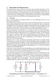
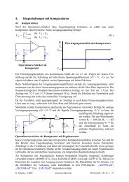
I MOOEL <strong>169</strong>TtlEORY OF OPERATIONSECTION 5.THEORY OF OPERATION5-1. GENERAL.5-6. SIGNAL CONDITIONING.II5-2. This section contains circuit descriptions forthe <strong>Model</strong> <strong>169</strong> OMM. An overall block diagram of signalflow is provided in Figur‘e 5-I. The overallschematic diagram, drawing 301800, is contained inSection 7 of this m~nudl.5-3. OVERALL OPERATION.5-4. As shown in Figure 5-1, the heart of the <strong>Model</strong><strong>169</strong> is d single chip A/D converter with built-inliquid crystal display drivers. The displayedreading is the ratio of two floating input voltagesto this converter. On all functions except ohms,one voltage (Reference) is IOOmV. The other voltage(VINHI) is the unknown input cuwent 01‘ voltageto the <strong>Model</strong> <strong>169</strong> which is converted and/or scaled bythe input signal conditioning circuitry to a dcVoltage between zero and ?200m". The displayedreading is then determined by the formula: 1000(YINHI + VREFERENCE). The A/O Conwrteralso automatically determines the polarity of theinput signal and detects whether an overrangecondition exists (>1999 counts). A minus sign isdisplayed, plus is implied, and an ove~~ange isdisplayed by a I with the last three digits blanked.The annunciators ape displayed by the combination Ofrange dnd function switching, and the decimal pointis positioned by the range switching.5-5. For the ohms function, d reference resistor isplaced in series with the unknown resistor and avoltage is applied. Since the Same current flowsthrough both resistors, the ratio of their voltagesis the sdme as the ratio Of their resistances.Thus, the voltage w1‘oss each resistor is measuredby the A/O converter and their ratio is displayedper the formula: IO00 (VR, i VRREFERENCE).5-l. AC/DC Voltage Measure,wnts.5.8. For voltage measurements, ds shown in Figure5-2, the input is divided by 1, 10, 100, 1000, or10,000 by the IO megohm resistive divider. Theresulting output from the divider is d 0 to 200mVvoltage. For a dc input, this voltage is applieddirect to the A/D co"vel‘teP along with the IOOmYreference. It should be noted that, since no activegain or attenuator stages are used. the dc dccurdcyis determined primarily by the precision resistoraccuracies (actually their ratios) and the referenceadJ"stment.5-9. For an x input, the output of the resistivedivider is first applied to the AC Converter. TheAC conver‘ter is a half wave rectifier with IOOUVresolution and sufficient gain to provide d positivedc output voltage equivalent to the nns value of dsinusoidal input. Thus, for sinusoidal input oflOOmVac, the output will be IOOmVdc. The importantgain determining elements of the converter dwprecision resistors so that d gain adjustment is notrequired.5-10. AC/DC Current lkasuremnt.5-11. FOT Current medsurements, its Shown in Figure5-3, the appropriate shunt resistor is placed acrossthe OMM input in accordance with the selected range.As with voltage medsurcments, the voltage dropacross the current shunt is designed to be 2OOmV fora full scale input current on any range. Therefore,after the input current is converted to d voltage,the meaSUPement process for current is identical tothat for voltage measurements. Accuracy for dcCurrent meaSurCments is primarily determined by theilccUrXies of the precision shunt resistors and thereference adjustment. These two items also affectac accuracy along with any error contributed by theAC Converter.5-1