physical and functional considerations (Chai, 1995). Similarly, the aircraft inertiasare calculated from a build-up based on each component inertias calculated fromthe mean c.g. location for each component.• Aerodynamics: The general aerodynamic characteristics and stability derivativesare calculated in this discipline. Induced, parasite and wave drag calculations areconsidered. To provide greater flexibility and accuracy in the calculation of aerodynamiccharacteristics, semi-empirical models and a nonplanar, multiple liftingsurface panel method are implemented. The induced drag is calculated from parametrictechnology models and the panel method. Parasite drag is calculated usinga detailed component build-up (Roskam, 1998) taking into consideration viscousseparation and components mutual interference effects. Transonic wave drag ismodeled based on Lock’s empirical approximation, using the Korn equation extendedby Mason to include sweep (Malone et al., 1995). Downwash effects andstability derivatives are calculated from a combination of semi-empirical formulae((Fink, 1975), (ESDU, 1987)) and lifting panel method results. The ground effecton induced drag has been taken into account using simplified empirical formulationssuch as those used in Hoerner et al., 1975, while the effect on lift and pitchingmoment characteristics has been taken into account using both a semi-empiricalformulation as presented in Roskam, 1998, and a image mirror technique for theimplemented panel method.• Performance: <strong>Aircraft</strong> performance characteristics are analyzed for each flight missionsegment as shown on Fig. 5. Field distances, rate of climb, and range arecalculated based either on analytical expressions or numerical simulations. Thelanding field length is calculated assuming a landing weight of 90% MTOW. Specificair range is calculated based on the Breguet’s equation, for the given aircrafttotal and fuel weights, lift and drag coefficients, specific fuel consumption, altitudeand Mach number.• Propulsion: Propulsion characteristics, such as engine weight, thrust and specificfuel consumption for a given altitude and Mach number, are calculated based onengine scaling of a baseline PW-2037 turbofan engine.• Flight Dynamics and <strong>Control</strong>: It is assumed that all aircraft states are measurablewithout noise. <strong>Longitudinal</strong> design constraining, open-loop, and closed-loop analysesare performed at each flight mission segment as shown on Fig. 5. <strong>Control</strong> designis performed for all in-flight phases (climb, cruise, and landing approach) of themission profile.Among the longitudinal modes the short period response is of prime concern dueto its rapid response and its correlation with handling qualities evaluation. For thisreason, we concentrate our efforts in the stability augmentation of this mode. Thelongitudinal short period flight dynamics equations can be formulated as:10
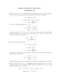
[ ] [ ] [ ] [ ]Zα/= V 1 α Zα/ ˙α˙q M α + M + V˙αZ α / V M q + M ˙αq M δ + M [δ˙αZ e ] (6)δ / Vwhere α is the aircraft angle of attack, q is the aircraft pitch rate, δ e is the elevatordeflection angle, V is the aircraft frestream velocity, and [Z α ,M α ,M ˙α ,M q ,Z δ ,M δ ]are dimentional stability derivatives. Note that every dynamic state is affected bythe elevator deflection control input signal.<strong>Control</strong> Systems <strong>Design</strong>The control system considered consist of an output feedback controller, where the gainscan be expressed as:[ ]αu = δ e = [k α ,k q ](7)qwhere stability of the closed loop system is guaranteed by selecting negative control gainvalues as seen in Fig. 7.150Root Locus2Root Locus100α/δ e1.5q/δ e1Imaginary Axis500-50-100Imaginary Axis0.50-0.5-1-1.5-150-300 -250 -200 -150 -100 -50 0Real Axis-2-3 -2.5 -2 -1.5 -1 -0.5 0Real AxisFig. 7: Root Locus of the Closed Loop System<strong>Design</strong> VariablesTable 2 lists the design variables, their bounds, and the initial design used in the optimizationproblem. Note that most of the coupling variables described will be repeatedfor each flight condition analyzed. At the system level, 61 design variables are takeninto consideration, from which 19 are global design variables and 42 are coupling designvariables. The global design variables include the main non-dimensional geometricvariables which define the aircraft configuration. Coupling variables include 4 flight conditionindependent terms (engine scaling factor, MTOW, fuel and engine weights), whilethe rest are distributed over the different flight conditions. For example, 12 coupling11