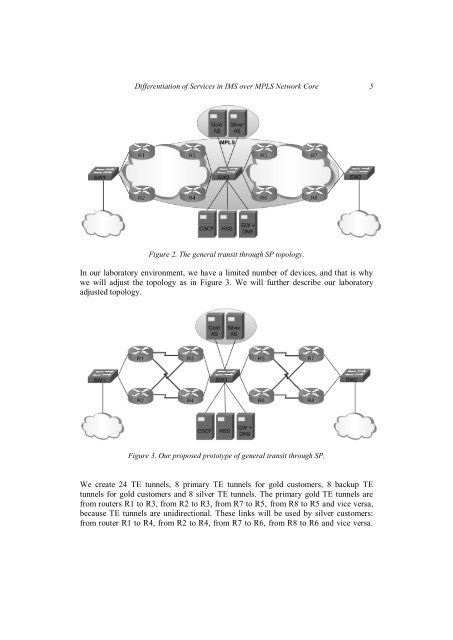
4 Filip BURDA, Peter HAVRILA, Marián KNĚZEK, Klaudia KONÔPKOVÁ, JurajNEMEČEK, Ján MURÁNYIFirst, it focuses on provid<strong>in</strong>g session control us<strong>in</strong>g a standardized set <strong>of</strong> servicescalled functions. These functions are distributed among various nodes with<strong>in</strong> thenetwork core and each function is responsible for a different set <strong>of</strong> operations,<strong>in</strong>clud<strong>in</strong>g authentication, authorization, registration, media handl<strong>in</strong>g, rout<strong>in</strong>g andservice provision<strong>in</strong>g.Its second ma<strong>in</strong> feature is the architecture's ability to add services to the network<strong>in</strong> a well-def<strong>in</strong>ed and scalable manner. These services are implemented <strong>in</strong> so-calledapplication servers and can provide a vast amount <strong>of</strong> features for the network'ssubscribers to utilize. Even <strong>in</strong> the current early stages <strong>of</strong> <strong>IMS</strong> <strong>in</strong>tegration, there arealready application servers with the ability to provide presence notification, IPTVstream<strong>in</strong>g, Video-on-Demand or <strong>in</strong>stant messag<strong>in</strong>g services. The amount <strong>of</strong> servicesand their <strong>in</strong>tegration with other services commonly available <strong>over</strong> the Internet isexpected to rapidly grow <strong>in</strong> the near future [7]. All this is implemented upon robustand tested protocols <strong>of</strong> the TCP/IP stack.Another important feature <strong>of</strong> the <strong>IMS</strong> network is its openness and focus on<strong>in</strong>teroperability. The primary communication protocol <strong>in</strong> the <strong>IMS</strong> network is theSession Initiation Protocol (SIP). S<strong>in</strong>ce this protocol is standard-based, this allows theoperator to construct parts <strong>of</strong> his <strong>IMS</strong> network us<strong>in</strong>g components and s<strong>of</strong>tware fromdifferent vendors, thus form<strong>in</strong>g a more competitive market. From the operator's po<strong>in</strong>t<strong>of</strong>-view,this feature makes <strong>in</strong>vestments <strong>in</strong> an upgrade to <strong>IMS</strong>, as opposed to currentlegacy network architectures and their closed-vendor nature, very feasible.The last important reason why <strong>IMS</strong> is expected to supersede any other form <strong>of</strong><strong>in</strong>telligent telecommunication network is the architecture's ability to use legacynetworks as part <strong>of</strong> the doma<strong>in</strong> core. This means the operator does not have to startimplement<strong>in</strong>g <strong>IMS</strong> network from scratch, but can <strong>in</strong>stead evolve his current legacynetworks to IP-based <strong>in</strong> small steps. Rather than be<strong>in</strong>g just a technology concept, thisfeature turns the <strong>IMS</strong> architecture <strong>in</strong>to a appeal<strong>in</strong>g bus<strong>in</strong>ess case which can bef<strong>in</strong>ancially justified.3 Topology descriptionIn Figure 2, the test-bed <strong>of</strong> <strong>IMS</strong> core with the surround<strong>in</strong>g redundant carrier network ispresented. The carrier network is composed <strong>of</strong> many routers with multiple redundantl<strong>in</strong>ks. We have two exit po<strong>in</strong>ts <strong>in</strong> our network to simulate transit SP (Service Provider).One exit po<strong>in</strong>t is on the far left side, and one on the far right side. <strong>IMS</strong> core is situated<strong>in</strong> the network center.
<strong>Differentiation</strong> <strong>of</strong> <strong>Services</strong> <strong>in</strong> <strong>IMS</strong> <strong>over</strong> <strong>MPLS</strong> <strong>Network</strong> <strong>Core</strong> 5Figure 2. The general transit through SP topology.In our laboratory environment, we have a limited number <strong>of</strong> devices, and that is whywe will adjust the topology as <strong>in</strong> Figure 3. We will further describe our laboratoryadjusted topology.Figure 3. Our proposed prototype <strong>of</strong> general transit through SP.We create 24 TE tunnels, 8 primary TE tunnels for gold customers, 8 backup TEtunnels for gold customers and 8 silver TE tunnels. The primary gold TE tunnels arefrom routers R1 to R3, from R2 to R3, from R7 to R5, from R8 to R5 and vice versa,because TE tunnels are unidirectional. These l<strong>in</strong>ks will be used by silver customers:from router R1 to R4, from R2 to R4, from R7 to R6, from R8 to R6 and vice versa.