ERIKS Maintenance and Condition Monitoring Technical ... - Eriks UK
ERIKS Maintenance and Condition Monitoring Technical ... - Eriks UK
ERIKS Maintenance and Condition Monitoring Technical ... - Eriks UK

Create successful ePaper yourself
Turn your PDF publications into a flip-book with our unique Google optimized e-Paper software.
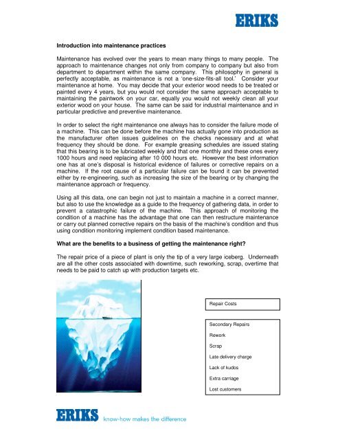
Introduction into maintenance practices<strong>Maintenance</strong> has evolved over the years to mean many things to many people. Theapproach to maintenance changes not only from company to company but also fromdepartment to department within the same company. This philosophy in general isperfectly acceptable, as maintenance is not a ‘one-size-fits-all tool.’ Consider yourmaintenance at home. You may decide that your exterior wood needs to be treated orpainted every 4 years, but you would not consider the same approach acceptable tomaintaining the paintwork on your car, equally you would not weekly clean all yourexterior wood on your house. The same can be said for industrial maintenance <strong>and</strong> inparticular predictive <strong>and</strong> preventive maintenance.In order to select the right maintenance one always has to consider the failure mode ofa machine. This can be done before the machine has actually gone into production asthe manufacturer often issues guidelines on the checks necessary <strong>and</strong> at whatfrequency they should be done. For example greasing schedules are issued statingthat this bearing is to be lubricated weekly <strong>and</strong> that one monthly <strong>and</strong> these ones every1000 hours <strong>and</strong> need replacing after 10 000 hours etc. However the best informationone has at one’s disposal is historical evidence of failures or corrective repairs on amachine. If the root cause of a particular failure can be found it can be preventedeither by re-engineering, such as increasing the size of the bearing or by changing themaintenance approach or frequency.Using all this data, one can begin not just to maintain a machine in a correct manner,but also to use the knowledge as a guide to the frequency of gathering data, in order toprevent a catastrophic failure of the machine. This approach of monitoring thecondition of a machine has the advantage that one can then restructure maintenanceor carry out planned corrective repairs on the basis of the machine’s condition <strong>and</strong> thususing condition monitoring implement condition based maintenance.What are the benefits to a business of getting the maintenance right?The repair price of a piece of plant is only the tip of a very large iceberg. Underneathare all the other costs associated with downtime, such reworking, scrap, overtime thatneeds to be paid to catch up with production targets etc.Repair CostsSecondary RepairsReworkScrapLate delivery chargeLack of kudosExtra carriageLost customers
The ultimate price can be paid if the maintenance philosophy <strong>and</strong> culture is not right.However if machine reliability is increased then production can be increased <strong>and</strong> thenthe nice prospect of finding new customers for the more products that you can make,the price of manufacturing is reduced thus profitability is increased. The following aregenuine graphs that were submitted to <strong>ERIKS</strong> from an aluminium casting <strong>and</strong> rollingcompany.This customer applied all forms of good maintenance practices to including ReliabilityCentred <strong>Maintenance</strong>, Total Production <strong>Maintenance</strong>, Kaizen, ContinuousImprovement Teams, Crosby <strong>and</strong> <strong>Condition</strong> Based <strong>Maintenance</strong>. This took totalcommitment from the operators through to the managing director. This plant is nowone of the most efficient in the group though its machinery is one of the oldest. Thesuccess of a good maintenance regime can be measured in the change in failure modeof machines over time; here is the failure mode graph for electric motors at the samealuminium company.
One can see that the percentage of units that failed has been reduced from 50% to20% <strong>and</strong> that almost 80% of all motors are now sent in for an overhaul as opposed to afailure compared with 40% ten years prior. In that time production has increased <strong>and</strong>new plant has been purchased thus increasing the number of motors on site. We canlook at the total number of motor repairs.The total reduction in the number of repairs is evident.
What is condition monitoring <strong>and</strong> where is its role in maintenance?One definition of condition monitoring is, “The collection, storage, comparison, <strong>and</strong>evaluation of data taken from a machine to establish the running condition of thatmachine.“The data could be made up of several parameters. For example, looseness/play dueto mechanical wear, electric current, pressure, surface finish brush wear, vibration <strong>and</strong>temperature, to name a few.A database needs to be initialised, itemising the data to be collected from the individualcomponents of a machine <strong>and</strong> what frequency that data needs to be taken. Thefrequency of the data acquisition is dependant upon several factors.• Criticality of machine to production – cost of downtime• Cost of damage to machine from individual component failure• Time to repair or replace component• Criticality of component within the machine• The failure mode, failure rate <strong>and</strong> time between failures• The maintenance needed on the item <strong>and</strong> its frequency <strong>and</strong> method ofmaintenance• Access to specialised data acquisition equipment• Access to machineryThis data is then evaluated against known set limits for that machine, based oninternational st<strong>and</strong>ards, manufacturers guidelines or previous repairs on that machineor similar machines.Knowing the correct frequency of data collection along with the correct warningcondition levels are the key to any successful condition monitoring regime. Considerthe following parameter measurement trend graph.141210864ParameterCritical AlarmWarning Alarm2001/01/200101/02/200101/03/200101/04/200101/05/200101/06/200101/07/200101/08/200101/09/200101/10/200101/11/200101/12/2001
If we knew that the critical alarm was 12, then there was no warning of failure due tothe steepness of the failure curve until the last reading, <strong>and</strong> we are now in a panicsituation, which could with a better data acquisition approach have been avoided. Wecan reduce the warning alarm to 7.5; this would have given rise to several false alarms.1 41 21 086P a ram e terC ritic a l A la rmW a rn in g A la rm42001/01/0101/02/0101/03/0101/04/0101/05/0101/06/0101/07/0101/08/0101/09/0101/10/0101/11/0101/12/01However that ‘false alarm could have alerted us to take more data more often at thosetimes or even done a machine inspection. If the machine inspections had foundnothing then the alarm would have to be re-evaluated otherwise a “cry wolf” situationwould exist. There are two further solutions for this problem. The first is to protect themachine, for instance if we were reading a pressure gauge we could fit a sensor wiredto a PLC which would then compliment, not replace, our monthly data acquisitions.The second is to take data more frequently especially as we can see that theparameter curve is getting steeper after each reduction.14121086Param eterCritical AlarmW arning Alarm42001/01/0101/02/0101/03/0101/04/0101/05/0101/06/0101/07/0101/08/0101/09/0101/10/0101/11/0101/12/01The constant fine-tuning of the data acquisition frequency <strong>and</strong> method are key parts ofany condition based maintenance programme.
What are the tools of condition monitoring for condition based maintenance?COMMUNICATIONThe primary tool for any condition based maintenance <strong>and</strong> for any maintenance that is,is communication. One can take the best data using the latest technology but if it goesnowhere for interpretation or its interpretation is not acted upon then it is useless.Communication has to flow in all directions, if a diagnosis of some data says that aproblem exists with coupling <strong>and</strong> on inspection it is found that the shaft is eccentricthen that information needs to be sent back to the analysis. Communication has toexist between the data parameters, the electrician needs to know that the filters havebeen changed on a fan unit in case he experiences current changes in his data.ANALYSISDATAACQUISITIONCONDITION BASED MAINTENANCEINSPECTIONCORRECTIONORFEEDBACKThis constant information flow is the life-blood of the programme. Without theinformation links the system will collapse, regardless of how good any of the individualelements are in the chain.INSPECTIONS / DATA ACQUISITIONA lot of companies are doing more condition monitoring than they actually know.Many companies carry out a planned maintenance regime of testing this, inspectingthat <strong>and</strong> checking the other. Reports are sent back into the maintenance managementsystem saying that the item is worn but serviceable, that there is backlash present butit is still okay or that the oil level is acceptable. The very fact that feedback is beingissued is commendable, but the one thing missing from all the reports is data. What isworn? Has it decayed since the last inspection? What is still serviceable? How long tillwe need to replace it? What is acceptable? Are we getting less acceptable by theday? The statements in the feedback lead to the follow up questions. It would bebetter to say that the item has grooves in it that are approximately 1mm deep across10mm of the surface, there was ¼ turn of backlash on the input shaft, <strong>and</strong> the oil is ¾of the way between min <strong>and</strong> max.The subjectivity needs to be replaced with objectivity. With reliable tangible datacomes the ability to compare <strong>and</strong> plot the results <strong>and</strong> eventually predict the potentialfailure <strong>and</strong> thus ensure that any corrective action that can be implemented to extendthe lead-time to failure or prevent the failure. Inspection procedures therefore need tobe written to ensure that when data is being acquired it is collected using the samemethod each time. The same data needs to be taken using the same instrument, from
the same point under the same conditions. Where any of these conditions differ thenthat is recorded <strong>and</strong> stored separately this can be used for judgement against wherethose conditions exist again.The types of inspections can be numerous; most of them though can be done usingengineering instruments such as the dial test indicator or by reading gauges or dials onthe machine. The dial <strong>and</strong> gauge data collection can be incorporated into anoperator’s TPM inspection at the start of a shift, whilst more complex checks need todone by engineers.<strong>ERIKS</strong>’s <strong>Condition</strong> <strong>Monitoring</strong> Services.From the above discussion it is clear that a lot of condition monitoring <strong>and</strong> conditionbased maintenance could be being done in a factory by the company’s own personnel.However due to capital outlay or resource constraints certain forms of conditionmonitoring may need to be done by an outside consultant. <strong>ERIKS</strong> offer a very widerange of condition monitoring services including:• Vibration data collection <strong>and</strong> analysis• Thermographic surveys• Electrical, lubrication <strong>and</strong> hydraulic oil analysis• Electrical Signature Analysis• General inspectionsVIBRATION DATA COLLECTION AND ANALYSIS SURVEYSVibration is the response of a system to an internal or external stimulus causing it tooscillate. While it is commonly thought that vibration itself damages machines, it doesnot. Instead it is the damage done by dynamic stress that causes fatigue of thematerials: the dynamic stresses are caused by vibration. That is to say that differentmachines have a different toleration tovibration.There are literally hundreds of specificproblems that can cause a machine toexhibit excessive vibration. To locatethe root cause of vibration an analysisof the vibration is required. The forcesthat cause vibration are usuallygenerated through the rotating motionof the machine’s parts or electricalsupply frequency. When a faultcondition occurs the problem willexhibit characteristics that are directlyrelated to these frequencies.As vibration is oscillating movement we could simply just measure the amount ofmovement in the system, this is called displacement.The displacement is usually expressed as the distance from one extreme of travel tothe other, or ‘peak to peak displacement’. The units of displacement are micrometers,µm, (0.001mm=1 micrometer). However displacement is related to the frequency. For
example 30µm at 1000Rpm is just as destructive as 300µm at 100Rpm. This makesthe setting of alarms cumbersome to evaluate machinery condition. It must beremembered that each source ofvibration contributes to the ultimatefatigue of the machine. The overallcondition of the machine can only bedetermined by an overall measurementof vibration that takes into considerationall frequencies of vibration withrelatively equal weighting. This isaccomplished by using the firstdifferential of vibration with relativelyequal weighting. This is accomplishedby using the first differential ofdisplacement, called vibration Velocity.If any item is struck it will tend to vibrateor ‘ring’ at its natural frequency. If a flaw exists on a bearing this will act like a tinyhammer <strong>and</strong> cause the bearing to ring at its natural frequency <strong>and</strong> whatever thebearing is connected to mechanically will ring at its’ natural frequency. The same istrue for a defective gear. To calculate all these natural frequencies would be atremendous task. The vibration data collectors used by <strong>ERIKS</strong> filter out all frequenciesbelow a set value, (usually 300 000Cpm (5kHz), but can be varied) then take theoverall amplitude of the remainder. This gives a reading that is directly proportional tothe amount of metal-to-metal contact in a system. The unit given to this reading is gSE,gE peak-vue (dependant upon equipment manufacturer As it is a high frequencyreading spike energy does not travel very far, thus wherever the highest spike energyreading is, is where the highest amount of metal-to-metal contact exists. If this unit isplotted with respect to time then a trend of the metal-to-metal contact is possible, thusgiving bearing or gear condition.In order to analyse a vibration it needs to be converted into an electrical signal. To dothis a vibration transducer is used. The first vibration transducers were shaft-ridingsticks with a magnet on the opposite end surrounded by a coil to produce an electricalsignal. This is known as a ‘displaceometer’ as its native units are displacement. Thenext generation of vibration transducers used spring-loaded magnets inside a coil toproduce an electrical signal, these are known as ‘velocometers’. The most commonsensors in use nowadays are based on piezoelectric technology, a weight inside thetransducer is pressed against a series of piezoelectric discs <strong>and</strong> an electric signal isproduced proportional to the vibration. These transducers are called accelerometers.All these transducers are still in use today, but the majority of data collectors useaccelerometers.The transducers can be fitted to machines <strong>and</strong> have their output monitored either byprotection systems or if specified before installation the machine’s own PLC. Theoutputs can be 4-20mA or 0-10 Volts <strong>and</strong> there are transducers that exist that will domulti-dimensional data, that produce a signal respective to velocity <strong>and</strong> another for theenveloped (bearing condition) reading. The cost difference between a st<strong>and</strong>ard (aconly) transducer <strong>and</strong> a conditioned (4-20mA, 0-10 V) is minimal <strong>and</strong> should always beconsidered when fitting fixed transducers.Once a signal is obtained using a transducer it is just a matter of using signalprocessing techniques to store, filter <strong>and</strong> break down the signal into its component
frequencies. There is a need to get as close to the bearing housing as possible to takethe vibration reading. The accelerometers are usually portable mounted magneticallyor they can be installed permanently if guarding does not permit access.Once a signal is obtained it is converted using a Fast Fourier’s Transform into avibration spectrum→This enables all the individual frequencies to be analysed <strong>and</strong> alarmed to detect anychanges that have occurred between readings. The original vibration waveform signal,if possible, will be stored without averages, as there is a huge value in the datacollected when looking for transient defects or non-synchronous eventsIf possible we take vertical, horizontal <strong>and</strong> axial velocity readings on each bearing inthe system. Unfortunately access problems such as coupling <strong>and</strong> belt guards meanthat it is not always possible to obtainall the readings.To use vibration as a trending tool forcondition monitoring a regularprogramme of data collection isnecessary, but vibration analysis canbe useful at locating problems on amachine, some data collectors can beconnected to strobe lights to ‘stop’ thecomponent that is vibrating, otherscan have an input from a lasertachometer to carry out start up <strong>and</strong>coast down tests to locate momentsof resonance <strong>and</strong> critical speeds.These are classed as analytical tools<strong>and</strong> usually do not form part of routinevibration data collection <strong>and</strong> analysis.To set up a new vibration database an initial survey of the site is needed. Data isacquired from the machines as to the number of measurement points required, speedsof shafts <strong>and</strong> type of machine. A database would then be written on a computer withroutes that are loaded into a data collector. An engineer then tours the plant with thedata collector <strong>and</strong> captures the vibration data. Once all the data is collected it is thendownloaded into the computer. The data is then analysed. More data may be takento confirm analysis <strong>and</strong> recommendations submitted. The report is written <strong>and</strong> isusually with a customer within 5 working days.
THERMOGRAPHIC SURVEYSThe basis of infrared thermography is quite simple. All objects emit heat or infraredelectromagnetic energy, but only a very small portion of this energy is visible to oureyes. In order to see the heat being emitted, an infrared camera must be used. Thecamera detects the invisible thermal energy <strong>and</strong> converts it to a visible image, whichthen allows <strong>ERIKS</strong>’s thermographerto interpret the image.Obviously in order for an image tobe obtained access must be gainedto the surveying area, such as theopening of electrical controlcabinets. If problems occurobtaining such access then <strong>ERIKS</strong>has the solution Thermal ImagingWindows, which can be fitted tomost applications during a deadshift<strong>and</strong> left in-situ for futuresurveys.The primary purpose for an<strong>ERIKS</strong>’s Infrared ThermographicInspection Programme is to reducethe number of costly, unscheduled shutdowns that could occur, <strong>and</strong> to prevent damageby detecting equipment failure in its early stages. However, infrared thermography canalso enhance productivity <strong>and</strong> save money by locating areas of poor performance.
Benefits of having an inspection:• Locates problems quickly without interruptingservices or production• Reduces costly, unscheduled interruptions due topower outages• Aids maintenance staff• Extends the life of equipment by locatingproblematic components prior to catastrophicfailure• Checks equipment for problems before thewarranty has expired• Confirms that appropriate repairs have beencompletedNecessary replacement parts for repairs can beordered ahead of time, so interruptions are kept to aminimumAs the thermal imaging cameras are real timeproblems are found immediately <strong>and</strong> solutions areoffered, before the <strong>ERIKS</strong> engineer leaves site. A fullreport will then follow listing the areas surveyed <strong>and</strong> full colour thermograms <strong>and</strong> digitalphotographs of the faults found.Within the report you will find accurate plant locations <strong>and</strong> real engineeringrecommendations to eliminate the problem.
<strong>Condition</strong> <strong>Monitoring</strong> by Oil AnalysisAny machine that uses oil as a lubricant, insulator or power medium can have theircondition monitored by taking periodic samples of that oilLubrication oils used in gearboxes <strong>and</strong> bearings are tested for moisture, changes inviscosity, contamination <strong>and</strong> wear components. The presence <strong>and</strong> identification ofwear particles can not only give indication that the unit has worn but which part hasworn.<strong>Monitoring</strong> the condition of the lubricant in gearboxes has an advantage over vibrationanalysis on slower speed items. Vibration on slow speed shafts is very timeconsuming <strong>and</strong> very difficult due to the duration of a ‘pulse’ or ‘knock’ with respect tothe time taken for a shaft to rotate. The debris in lubrication oil will be from all theshafts in the drive train that share that oil <strong>and</strong> therefore has no bias towards speed.When you put the two technologies together you get a wonderful overview of thecondition of the machine.Electrical oils used in transformers <strong>and</strong> switch-gear are tested for electrolytic strength,water content, acidity <strong>and</strong> discolouration, regular sampling can again give earlywarning of a critical failure <strong>and</strong> also give causes for the impending failure.Once found, a fault may be rectified by <strong>ERIKS</strong>’s own transformer filtration equipment,which can cleanse an oil on-site without having to remove the transformerElectrical switchgear oil is monitored regular by <strong>ERIKS</strong> under a switchgearmaintenance contract whereby <strong>ERIKS</strong> carry out all routine switchgear maintenancerequired under statutory regulations.
The efficiency of hydraulic oil is critical to any fluid power system as all the force isexerted using the oil. If the oil is not fit for the purpose then the equipment will notfunction in an efficient manner. Debris will damage the pump impellor, filters <strong>and</strong>cylinders, this further damage will cause further debris <strong>and</strong> more damage. cylinders oroil for any application can be found within the <strong>ERIKS</strong> Fluid Power Division, which hasits own laboratory <strong>and</strong> team of technicians.Advice on selecting the correct filter oil <strong>and</strong> system for the application are all availablein-house within <strong>ERIKS</strong>Electrical Signature Analysis<strong>ERIKS</strong>’s electrical signatureanalysis service is offered invarious forms, low voltage, highvoltage, on-line <strong>and</strong> off-line.Motor current signature analysis isdone on-line <strong>and</strong> involves taking afull spectral breakdown of thesupply current to a motor <strong>and</strong>looking for small modulations inthat signal that can be caused byrotor defects, supply faults <strong>and</strong>stator eccentricities. It involvesdata being taken by a verysensitive current transducer that isconnected to a signal processor.The data is then stored, analysed <strong>and</strong> a report is written offering recommendations.The service can be done on high voltage <strong>and</strong> low voltage motors, squirrel cage,synchronous or wound rotor types. There are safety implications of gaining access toa suitable monitoring point, but these can be overcome with the usual approach of riskassessment <strong>and</strong> method statementThe life expectancy of aHigh Voltage machinewill depend on variousfactors acting eithersingly or in combinationto modify the dischargecharacteristic of thewinding.This is why <strong>ERIKS</strong> usingtheir own in-housemanufactured ‘RogowskiCoil’ method ofgathering <strong>and</strong> analysing partial discharge activity is able to accurately predict thedegradation process <strong>and</strong> the effect discharge erosion plays on the stator insulationsystem.
The Rogowski Coil is totally non-invasive, requiring no direct connection to the HighVoltage circuit, <strong>and</strong> provides natural rejection of discharge signals generated by othermachines connected to the same supply system.ROGOWSKI COIL Partial Discharge Analysis will detect:-• Surface Contamination. - The accumulation of contamination on the surface ofthe endwindings reduces the resistivity of the winding.• Internal Discharge Detects. - Voids in the insulation structure.• Inter-Phase Discharge. - Measures <strong>and</strong> detects phase-phase discharges• Surface Tracking. - Surface contamination may permit the flow of substantialcurrent in the surface film leading to carbonisation of the underlying insulationsurface.• End Winding Movement. - Brought about by severe starting duties leading tofatigue failure of the tape structure.Slot Section Movement. - Loose Slot Wedges allowing tangential vibration at rotor slotpassing frequency, causing abrasion of the coil sides against the slot wall.ConclusionThis document set out to cut through some of the jargon associated with integrated <strong>and</strong>preventive maintenance along with trying to offer succinct overviews of the toolsinvolved.The most important tool in maintenance has to be communication <strong>and</strong> however it isdressed up (TPM, TQM WCM…) people need to communicate. <strong>ERIKS</strong> have had hadtheir biggest successes when all their services are brought to a site <strong>and</strong> sitecomplimenting not replacing the customer’s knowledge <strong>and</strong> experience of the plant.To this end SKF Reliability Systems awarded <strong>ERIKS</strong> the status of Certified<strong>Maintenance</strong> Partner in 2006 recognising the ethics, culture <strong>and</strong> competence of the
<strong>ERIKS</strong> condition monitoring business. So often one sees condition monitoring done inisolation to maintenance <strong>and</strong> the poor condition monitoring technician is trying his bestto set up a database with no information on the plant construction or productionrequirements <strong>and</strong> little information is then fed back to him regarding his correctiveaction. It is little wonder that the system then fails <strong>and</strong> unfortunately the blame thensits, wrongly, with the condition monitoring technician or the technology itself. Theadvent of ISO 18436, the certifying of the condition monitoring technician’scompetence, should not only increase the trust that clients put into the conditionmonitoring technologies <strong>and</strong> services, but also because of its code of ethics, mean thata level playing field exists between certified engineers, to avoid under <strong>and</strong> overselling.Over the years many sledgehammers have been used to crack nuts, but it is theunderselling that is the most worrying. Databases have been setup deliberately to takedata quicker, reporting time has been reduced to the point that little or no analysistakes place, combine the two <strong>and</strong> you have a recipe for disaster. Add to this theplethora of on-line systems that are out there as each supplier claims they have thecorrect system for any situation <strong>ERIKS</strong> are happy to be in a position to look across thewhole market to find the right solution to solve the customer’s problem.About the authorDavid Manning-Ohren is a time served maintenance electrician who on completing hisapprenticeship then went to work for <strong>ERIKS</strong> electromechanical services as a tester/electrical fitter. He soon built up a reputation for fault finding on-site being able tobridge the gap between electric motor repair shop <strong>and</strong> a customer’s production facility.When a motor management contract arrived David was in the perfect position to set up<strong>and</strong> run the contract. During that time he under went training in condition monitoringtechniques having to study <strong>and</strong> apply them in a cost-effective manner. A conditionmonitoring department was soon set up <strong>and</strong> David lead this time <strong>and</strong> further promotioninto regional <strong>and</strong> now national management followed. David now is the BusinessDevelopment Manager for <strong>Condition</strong> <strong>Monitoring</strong> for <strong>ERIKS</strong> <strong>UK</strong>. He also has a remitthat includes repairable asset management <strong>and</strong> assists in lubrication managementcontracts.