
You also want an ePaper? Increase the reach of your titles
YUMPU automatically turns print PDFs into web optimized ePapers that Google loves.
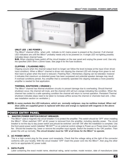
<strong>9B</strong><strong>SST</strong> 2 FIVE CHANNEL POWER AMPLIFIERUNLIT LED ( NO POWER )The <strong>9B</strong><strong>SST</strong> 2 channel LEDs, when unlit, indicate no AC mains power is present at the channel. If all channelLED indicators are unlit the <strong>9B</strong><strong>SST</strong> 2 probably needs only to be powered on. A single LED not lighting possiblyindicates blown channel fuses.N.B. When checking fuses switch off the circuit breaker on the rear panel and unplug the power cord. Use onlythe specified 250V 5mm x 20mm fuses. See page 6 for the fuse locations.CLIPPING ( FLASHING RED )Clipping occurs when the channel output level no longer can follow the level increase at the input (Over driveninput condition). When a <strong>9B</strong><strong>SST</strong> 2 channel is driven into clipping the channel LED will change from green to redthen back to green when the level is reduced ( Flashing Red ). Momentary clipping can be tolerated, howeverit indicates that maximum un-distorted power has been surpassed and potential speaker damage may resultif overload conditions persist. Any amplifier that is constantly operated into clipping indicates a more powerfulamplifier is needed for that application.THERMAL SHUTDOWN ( ORANGE )The <strong>9B</strong><strong>SST</strong> 2 channel has thermal shutdown circuitry to prevent damage due to overheating. Should thermalshutdown occur, the channel will mute, and the channel LED will turn orange indicating this condition. When thechannel has cooled to a safe operating condition the channel will return to normal operation. Persistent Thermalshutdown indicates steps need to be taken to increase airflow across the channel or channels heat sink. ( Alsosee installation section on ventilation ).NOTE: In some markets the LED indicators, which are normally red/green, may be red/blue instead. When red/blue LEDs are supplied green is replaced with blue and orange is replaced with magenta in the abovedescriptions.POWER ENTRY PANEL1. MASTER POWER SWITCH/CIRCUIT BREAKER.The <strong>9B</strong><strong>SST</strong> 2 uses a magnetic-trip circuit breaker (1) to protect the amplifier. This switch should be ‘OFF’ when installingthe <strong>9B</strong><strong>SST</strong> 2 . When switched ‘OFF’ all AC power is removed from the amplifier, including standby power. The circuitbreaker is not the day to day power switch and should be switched and left ‘ON’ after the installation is complete. Usethe front panel power switch (labelled "<strong>9B</strong> <strong>SST</strong> 2 ") or an external control voltage to Power-up or Power-down the amplifier.Should the breaker trip, lower or remove the amplifier input signals. Switch the breaker to the ‘ON’ position. Thenpower the unit up normally. The circuit breaker must be ‘ON’ at all times for the <strong>9B</strong><strong>SST</strong> 2 to operate.2. AC POWER INPUT.This is a high current plug for the power cord receptacle. Check that the voltage rating at the right of the connectorconforms with your locality. With the circuit breaker ‘OFF’ insert the power cord into the <strong>9B</strong><strong>SST</strong> 2 , then plug the otherend to an appropriate AC power outlet.3. DATA PLATELabel containing the exact model name, electrical rating, serial number, model revision, date of manufacture (date