Eddy Current Interaction of a Magnetic Dipole with a Translating ...
Eddy Current Interaction of a Magnetic Dipole with a Translating ...
Eddy Current Interaction of a Magnetic Dipole with a Translating ...

Create successful ePaper yourself
Turn your PDF publications into a flip-book with our unique Google optimized e-Paper software.
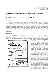
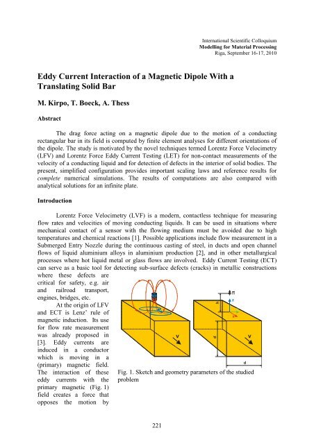
dhInternational Scientific ColloquiumModelling for Material ProcessingRiga, September 16-17, 2010<strong>Eddy</strong> <strong>Current</strong> <strong>Interaction</strong> <strong>of</strong> a <strong>Magnetic</strong> <strong>Dipole</strong> With a<strong>Translating</strong> Solid BarM. Kirpo, T. Boeck, A. ThessAbstractThe drag force acting on a magnetic dipole due to the motion <strong>of</strong> a conductingrectangular bar in its field is computed by finite element analyses for different orientations <strong>of</strong>the dipole. The study is motivated by the novel techniques termed Lorentz Force Velocimetry(LFV) and Lorentz Force <strong>Eddy</strong> <strong>Current</strong> Testing (LET) for non-contact measurements <strong>of</strong> thevelocity <strong>of</strong> a conducting liquid and for detection <strong>of</strong> defects in the interior <strong>of</strong> solid bodies. Thepresent, simplified configuration provides important scaling laws and reference results forcomplete numerical simulations. The results <strong>of</strong> computations are also compared <strong>with</strong>analytical solutions for an infinite plate.IntroductionLorentz Force Velocimetry (LVF) is a modern, contactless technique for measuringflow rates and velocities <strong>of</strong> moving conducting liquids. It can be used in situations wheremechanical contact <strong>of</strong> a sensor <strong>with</strong> the flowing medium must be avoided due to hightemperatures and chemical reactions [1]. Possible applications include flow measurement in aSubmerged Entry Nozzle during the continuous casting <strong>of</strong> steel, in ducts and open channelflows <strong>of</strong> liquid aluminium alloys in aluminium production [2], and in other metallurgicalprocesses where hot liquid metal or glass flows are involved. <strong>Eddy</strong> <strong>Current</strong> Testing (ECT)can serve as a basic tool for detecting sub-surface defects (cracks) in metallic constructionswhere these defects arecritical for safety, e.g. airand railroad transport,engines, bridges, etc.At the origin <strong>of</strong> LFVand ECT is Lenz‟ rule <strong>of</strong>magnetic induction. Its usefor flow rate measurementwas already proposed in[3]. <strong>Eddy</strong> currents areinduced in a conductorwhich is moving in a(primary) magnetic field.The interaction <strong>of</strong> theseeddy currents <strong>with</strong> theprimary magnetic (Fig. 1)field creates a force thatopposes the motion byNSvFig. 1. Sketch and geometry parameters <strong>of</strong> the studiedproblemmzxydv221
Lenz‟ rule. The magnetic system, which creates the primary magnetic field, experiences a dragforce acting along the direction <strong>of</strong> the conductor motion. Simple estimations show that this2force is F ~ vB , where is the electrical conductivity <strong>of</strong> the moving conductor, v=v x =constis the velocity and B is the magnetic induction. Measuring this force acting on the magneticsystem, allows us to measure the velocity <strong>of</strong> the moving conductor <strong>with</strong> high precision.The drag force increases quadratically <strong>with</strong> the magnetic induction. This allows one toincrease the sensitivity <strong>of</strong> this measurement technique by increasing the magnetic fieldintensity, whereby it can, in principle, be applied to poorly conducting bodies like electrolytes,ceramics or glass melts. However, this still requires research on the proper magnetic systemdesign and optimization as well as an accurate and advanced force measurement system.In general, one cannot find an analytical solution for the force acting on a realisticmagnet system even when the motion <strong>of</strong> the conducting body is very simple. Only a fewcases, which replace the real magnetic system by the magnetic dipole or simple coil, areknown to have analytical solutions [4, 5]. However, these simplified problems are veryimportant for LFV theory, because they allow a better understanding <strong>of</strong> the physics andprovide reference data for complex numerical simulations. In the present paper, we consider amoving rectangular conducting bar in a field <strong>of</strong> the magnetic dipole, which represents acanonical problem for LFV theory. It generalizes the case <strong>of</strong> an infinite conducting plate,which can be treated analytically [5]. Its solution can be directly compared <strong>with</strong> resultsobtained from LVF and ECT applications for duct flows and solids <strong>with</strong>out defects.1. Mathematical Formulation <strong>of</strong> the Problem and Numerical ProcedureWe consider an electrically conducting non-magnetic infinite solid bar <strong>with</strong> squarecross-section d×d (Fig. 1), which is moving <strong>with</strong> a constant velocity v in x direction in thefield B <strong>of</strong> a magnetic dipole <strong>with</strong> the magnetic dipole moment m . If the origin <strong>of</strong> thecoordinate system corresponds to the dipole location then the field <strong>of</strong> the dipole at distance r can be expressed as [6]:B 0 3( m r ) r m 5 . (1.1)4 r r 3<strong>Eddy</strong> currents are induced in the bar when it crosses the magnetic field lines. Theycreate a secondary magnetic field b . In this work, we assume that the magnetic diffusion timeis small and we can neglect the secondary magnetic field <strong>with</strong> respect to the primary magneticfield, i.e. the quasi-static approximation [7] is applied. It also means that for selected ranges <strong>of</strong>velocity v, electric conductivity and length scale h the magnetic Reynolds numberR m = 0 vh is small. The motion <strong>of</strong> the bar is prescribed, i.e. we consider the kinematicproblem.For the analysis we will use non-dimensional units based on the characteristic lengthL 0 =d, characteristic velocity equal to the bar velocity V 0 =v and the characteristic magnetic0mfield intensity B 0 =L 3. This selection <strong>of</strong> characteristic parameters leads to the following0 *2 3 *expressions for the current density j vB 0j and Lorentz force F vB0 L0Fwhere „star‟symbol represents non-dimensional quantities (omitted below).222
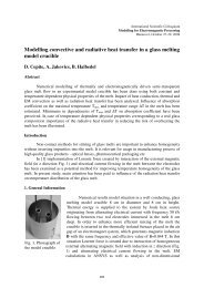
In the quasistatic approximation, the electric field can be represented as the gradient <strong>of</strong>the electrical potential . The induced current density can be expressed by Ohm‟s law formoving conductor as: j v B . (1.2)The moving bar is electrically neutral and according to the conservation <strong>of</strong> electriccharge, the induced currents should be divergence-free j 0 . Since the magnetic field <strong>of</strong>the dipole is solenoidal [6] and the velocity distribution uniform, the electrical potentialsatisfies the Laplace equation:2 0 . (1.3)A solution <strong>of</strong> this equation is required to obtain eddy currents using equation (1.2).Appropriate boundary conditions (BC) require zero normal currents on all side surfaces <strong>of</strong> the bar j n 0 . We also require that the electrical potential and currents should vanish at theremote ends.A general analyticalsolution <strong>of</strong> the problem<strong>with</strong> the described BCcould not be obtained.For this reason, anautomated Matlab TMscript coupled <strong>with</strong>the Comsol TM FEMLaplace „pardiso‟solver [8] was used toa) b)solve it numerically forthe electrical potentialFig. 2. Refined grid used for numerical simulations (the bar size using second orderis 7.5×1×1): a) a central part for z=const, b) x=constLagrangian elements[9]. The Lorentz forcewas later computed taking the volume integral <strong>of</strong> its density F j BdVor using the Biot-Savart law for secondary field computation at location <strong>of</strong> the dipole. The force and torque then can be found as F ( m)b and T mbcorrespondingly. The integration procedure wasimplemented using built-in Comsol TM functions.Our preliminary results showed that the accurate solution <strong>of</strong> the problem requires veryfine grid in a zone <strong>of</strong> large magnetic field gradients. Therefore, a refined grid (Fig. 2) wasused for simulations. We also assume that computational errors are acceptable if the distancebetween the dipole and the top surface <strong>of</strong> the moving bar h equals the doubled characteristicsize <strong>of</strong> the element. The computational grid was further refined for very small h≈810 -2 . Themaximal number <strong>of</strong> elements in the grid was around 10 5 .V223
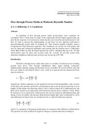
2. Results and DiscussionThe numerical results for the moving bar are compared to the analytically obtainedLorentz force F x 0 (h) for the translating infinite plate <strong>of</strong> identical thickness, where the dipole isvertically oriented [5]:30 1 h F x1 .3(2.1)128 h (1 h)3Tab. 1. Selected values <strong>of</strong> the F x /F x 0 curve for [0,0,1] oriented dipoleh 0.08 0.20 0.40 0.80 1.20 1.60 2.00 2.40 2.80 3.20 4.00F x /F x01.00 0.98 0.91 0.65 0.42 0.28 0.19 0.13 0.10 0.07 0.04Fig. 3. The ratio <strong>of</strong> rectangular crosssectionbar and infinite plate x forcecomponents acting on the magnetic dipolewhich is placed in the middle above thetop surface for different dipole orientationsFig. 4. Non-dimensional x forcecomponent acting on the magnetic dipolewhich is placed in the middle above thetop surface for different dipoleorientationsa) b) c)Fig. 5. Contours <strong>of</strong> non-dimensional current density magnitudes and current density vectorson the top surface <strong>of</strong> the bar for different orientations <strong>of</strong> the magnetic dipole: a) [1,0,0],b) [0,1,0], c) [0,0,1]. Only central part <strong>of</strong> the top surface is shownFor this case, the magnetic moment components are [0,0,1] in our non-dimensionalrepresentation. We consider three different orientations [1,0,0], [0,1,0] and [0,0,1]. Fig. 3 and224
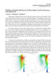
Tab. 1 present the ratio F x /F x0andFig. 4 the non-dimensional forceF x .The force ratio curve F x /F x 0 isdecreasing monotonously when his increased as expected. When htends to zero, i.e. the magneticdipole approaches the top surface<strong>of</strong> the bar, the curve reaches unityfor the vertically orientedmagnetic dipole. This resultconforms to expectations becausethe rectangular bar acts on thedipole exactly as the infinite plateif the dipole approaches itssurface. If the dipole is moved to anew position away from the barthen the force ratio starts to decayuntil it reaches very small valuesFig. 6. The ratio between the force acting on twodipoles and the force acting on one magnetic dipolebecause the “useful” volume under the influence <strong>of</strong> the magnetic dipole field decreases for therectangular bar when compared <strong>with</strong> the infinite plate. The part <strong>of</strong> the curve for h > 2 can beapproximated by a power law. A fit to the data provides F x /F x 0 = 0.76 h -2 . The same powerlaw approximation for F x (Fig. 4) gives F x ~ h -3 for small h and F x ~ h -5 for large hEquation(2.1) provides the estimate F x 0 ~ h -4 for the infinite plate, i.e. the Lorentz force decays fasterfor moving solid bar than for infinite plate.The other orientations <strong>of</strong> the magnetic dipole aligned <strong>with</strong> the coordinate system axesprovide smaller values <strong>of</strong> the Lorentz forces comparing to the infinite plate. The Lorentz forceon a dipole oriented in y direction is approximately ¼ part <strong>of</strong> the force for vertically orienteddipole because the magnetic field intensity is twice smaller and F x ~B 2 . If the dipole is orientedin x direction, then the force can reach 75% <strong>of</strong> the value obtained for vertically orienteddipole. This can be explained by the current density distribution in the bar (Fig. 5). It can beseen that the current density magnitude for [1,0,0] oriented dipole is higher than for [0,1,0]oriented dipole and the current density maximum is better localized in the region <strong>of</strong> thehighest magnetic field intensity for [1,0,0] oriented dipole.It is <strong>of</strong>ten required to increase the sensitivity <strong>of</strong> the LFV and the simplest way to makeit is to symmetrically introduce a second magnet from the other side (assuming that we cannotdecrease h or increase m) which in our case is represented as the second magnetic dipole <strong>with</strong>the same magnetic moment magnitude and the distance from the bar's closest surface. Bothdipoles have no shift in y direction and their magnetic moments are collinear to z axis.The numerical solution shows (Fig. 6) that the only one way to increase the Lorentzforce is to place the both dipoles unidirectionally. It can be seen that for small h values themagnetic field <strong>of</strong> each dipole is localized at the closest surface, i.e. both magnetic dipoleswork independently and we simply find a doubling <strong>of</strong> the force. With increasing h, themagnetic field is less localized and the Lorentz force increases if the dipoles haveunidirectional orientation or decays if the orientation is opposite. It is expected that theaddition <strong>of</strong> the second magnetic dipole will introduce four times greater Lorentz force forlarge h. This tendency can be clearly seen in Fig. 6.225
ConclusionsThe kinematic problem <strong>of</strong> a translating solid conducting body under the influence <strong>of</strong> amagnetic dipole has been investigated, where the dipole is located in the lateral mid-plane <strong>of</strong>the bar. The results show that the maximal Lorentz force can be obtained for the magneticdipole oriented in the vertical direction. The force depends on the distance h between dipoleand bar. It is given by power laws when the distance h is small or large compared <strong>with</strong> thewidth <strong>of</strong> the bar. For small distances, the power law is identical to the case <strong>of</strong> an infinite plate.At large distance, the power law for the bar shows a more rapid decay than for the infiniteplate. The proposed computational method can be applied to cylindrical solid body translationand to investigation <strong>of</strong> the kinematic problem <strong>of</strong> a laminar conducting flow.AcknowledgementThe authors gratefully acknowledge financial support from the Deutsche Forschungsgemeinschaftin the framework <strong>of</strong> the RTG Lorentz Force Velocimetry and <strong>Eddy</strong> <strong>Current</strong>Testing (grant GRK 1567/1).References[1] Thess, A., Votyakov, E., Kolesnikov Y.: Lorentz force velocimetry. Phys. Rew. Lett., Vol. 96, 2006, pp.164501.[2] Kolesnikov, Y., Karcher, C,. Thess, A.: Lorentz force flowmeter for liquid aluminium: Laboratoryexperiments and plant tests. Metallurgical and Materials Transactions B, in press.[3] Shercliff, J.: The Theory <strong>of</strong> Electromagnetic Flow Measurement. Cambridge University Press, Cambridge,UK, 1962.[4] Priede, J., Buchenau, D., Gerbeth, G.: Force-free and contactless sensor for electromagnetic flowratemeasurements. Magnetohydrodynamics, Vol. 45, 2009, pp. 451-458.[5] Thess, A., Votyakov, E., Knaepen, B., Zikanov, O.: Theory <strong>of</strong> the lorentz force flowmeter. New J. <strong>of</strong> Phys.,Vol. 9, 2007, pp. 299.[6] Jackson, J. D.: Classical Electrodynamics. John Wiley & Sons, New York, 1998.[7] Roberts, P. H.: An Introduction to Magnetohydrodynamics. American Elsevier Publishing Company, Inc.New York, 1967.[8] Petra, M., Gobbert, M., K.: Parallel Performance Studies for COMSOL Multiphysics Using Scripting andBatch Processing. Proceedings <strong>of</strong> the COMSOL Conference, Boston, 2009.[9] COMSOL Multiphysics Reference Guide, ver. 3.5a. Comsol AB, November 2008.AuthorsDr. Kirpo, MaksimDr. Boeck, ThomasPr<strong>of</strong>. Dr. Thess, AndrèInstitute <strong>of</strong> Thermodynamics and Fluid MechanicsIlmenau University <strong>of</strong> TechnologyP.O. Box 10056598684 Ilmenau, GermanyE-mail: Maksims.Kirpo@tu-ilmenau.de226