RF-Over-Fiber Links With Very Low Noise Figure - Photonic Systems ...
RF-Over-Fiber Links With Very Low Noise Figure - Photonic Systems ...
RF-Over-Fiber Links With Very Low Noise Figure - Photonic Systems ...

You also want an ePaper? Increase the reach of your titles
YUMPU automatically turns print PDFs into web optimized ePapers that Google loves.
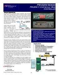
ACKERMAN et al.: <strong>RF</strong>-OVER-FIBER LINKS WITH VERY LOW NOISE FIGURE 2443Fig. 3. Equivalent circuit model for an external modulation link that includes thermal noise arising from ohmic loss in the traveling-wave electrodes ofaMach–Zehnder intensity modulator. : thermal noise spectral density arising from ohmic loss in the incremental length . Other parameters are asdefined in the caption of Fig. 1.of the two dashed curves in Fig. 2, which is a plot of an expressionderived in Section III, appears to confirm this hypothesis.The new terms and are derived in Sections III-C and III-D,respectively.III. IMPROVED ANALYTICAL MODEL OF LINK NOISE FIGUREIn this section, we derive an expression for link noise figurethat includes the effect of ohmic loss in a Mach–Zehnder intensitymodulator’s traveling-wave electrodes, yielding the lowerof the two dashed curves in Fig. 2.A. Effect of Electrode Loss on Link GainThe effect of the electrode loss on gain is reflected in (1)by the presence of the term. The modulator’s has afrequency dependence dictated largely by the frequency dependenceof loss in the electrodes (and, ultimately, on the extentto which the optical carrier and traveling-wave electrical signalvelocities match one another [5]; the analysis here assumes perfectvelocity matching), however, such thatis itself a function of fre-where the electrode loss coefficientquency [3], [5].(7)B. Effect of Electrode Loss on Thermal <strong>Noise</strong> FromTermination ResistanceIncluding electrode loss in the model has two effects on noisefigure. First, the expression for the effect of the thermal noisegenerated by the electrode termination resistance, which is representedby (4) for the lossless-electrode case, becomes morecomplicated [5]:Second, two new constant terms , arise from thermal noisegenerated by ohmic losses in the traveling-wave electrodes anddictate a minimum achievable noise figure exceeding what waspreviously postulated as the minimum in (3):(8)(9)C. Modulation of Co-Propagating Light by Electrode Thermal<strong>Noise</strong>We define the term in (9) as the portion of link noise figuredue to modulation of light by co-propagating thermal noise thatarises from loss in the modulator electrodes. We derive this termusing the equivalent circuit in Fig. 3, in which the electrodes aremodeled as a series of incremental pieces of transmission lineeach having length , characteristic impedance , and ohmicloss that results in thermal noise spectral density .Anywhere one “cuts” the traveling-wave electrodes in themodulator of Fig. 3 yields an impedance of looking intoeither of the two resulting sections of circuit. For instance, “cutting”the circuit between the end of the electrodes and the terminationresistance , the impedance looking towards the signalsource from the termination end of the electrodes is also .Therefore the spectral density of the noise imparted from theelectrodes to the termination load must equal 4 . Expressingthis conclusion mathematically(10)where the first term on the left-hand side of (10) is the source’sthermal noise density of 4 , which is attenuated byin the total length of transmission line, and where thesecond term on the left-hand side is the sum of all the incrementalthermal noise densities, each of which is attenuatedby a quantity appropriate to the distance that noise voltagespectral density must propagate along the electrodes to reachthe termination.Note that the thermal noise arising from loss in one section ofthe electrodes has no effect upon or relation to the noise arisingfrom loss in another section. Therefore, in (10) the contributionsof the noise sources from the individual incremental lengthsof lossy transmission line are tallied by summing the (scalar)squared magnitudes of the uncorrelated noise voltages. Tallyingby first summing the voltages themselves and then squaring thescalar magnitude of that vector sum would be appropriate onlyif the individual noise sources were correlated.Authorized licensed use limited to: Edward Ackerman. Downloaded on October 14, 2008 at 21:32 from IEEE Xplore. Restrictions apply.