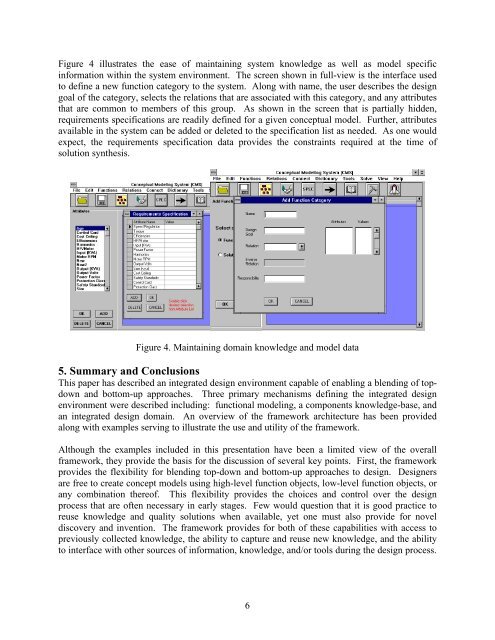
Figure 4 illustrates the ease of ma<strong>in</strong>ta<strong>in</strong><strong>in</strong>g system knowledge as well as model specific<strong>in</strong>formation with<strong>in</strong> the system environment. The screen shown <strong>in</strong> full-view is the <strong>in</strong>terface usedto def<strong>in</strong>e a new function category to the system. Along with name, the user describes the designgoal of the category, selects the relations that are associated with this category, <strong>and</strong> any attributesthat are common to members of this group. As shown <strong>in</strong> the screen that is partially hidden,requirements specifications are readily def<strong>in</strong>ed for a given conceptual model. Further, attributesavailable <strong>in</strong> the system can be added or deleted to the specification list as needed. As one wouldexpect, the requirements specification data provides the constra<strong>in</strong>ts required at the time ofsolution synthesis.Figure 4. Ma<strong>in</strong>ta<strong>in</strong><strong>in</strong>g doma<strong>in</strong> knowledge <strong>and</strong> model data5. Summary <strong>and</strong> ConclusionsThis paper has described an <strong>in</strong>tegrated design environment capable of enabl<strong>in</strong>g a blend<strong>in</strong>g of topdown<strong>and</strong> bottom-up approaches. Three primary mechanisms def<strong>in</strong><strong>in</strong>g the <strong>in</strong>tegrated designenvironment were described <strong>in</strong>clud<strong>in</strong>g: functional model<strong>in</strong>g, a components knowledge-base, <strong>and</strong>an <strong>in</strong>tegrated design doma<strong>in</strong>. An overview of the framework architecture has been providedalong with examples serv<strong>in</strong>g to illustrate the use <strong>and</strong> utility of the framework.Although the examples <strong>in</strong>cluded <strong>in</strong> this presentation have been a limited view of the overallframework, they provide the basis for the discussion of several key po<strong>in</strong>ts. First, the frameworkprovides the flexibility for blend<strong>in</strong>g top-down <strong>and</strong> bottom-up approaches to design. Designersare free to create concept models us<strong>in</strong>g high-level function objects, low-level function objects, orany comb<strong>in</strong>ation thereof. This flexibility provides the choices <strong>and</strong> control over the designprocess that are often necessary <strong>in</strong> early stages. Few would question that it is good practice toreuse knowledge <strong>and</strong> quality solutions when available, yet one must also provide for noveldiscovery <strong>and</strong> <strong>in</strong>vention. The framework provides for both of these capabilities with access topreviously collected knowledge, the ability to capture <strong>and</strong> reuse new knowledge, <strong>and</strong> the abilityto <strong>in</strong>terface with other sources of <strong>in</strong>formation, knowledge, <strong>and</strong>/or tools dur<strong>in</strong>g the design process.6
Further, the framework is generalizable. Although shown <strong>in</strong> relation to the design of powerconversion systems, the framework can be customized to a wide range of application doma<strong>in</strong>s.In each case, one would need to identify <strong>and</strong> capture the ‘language’ of the doma<strong>in</strong> with<strong>in</strong> thefunctions, categories, relations, <strong>and</strong> attributes def<strong>in</strong><strong>in</strong>g the framework. For example, consider theutility of the framework <strong>and</strong> model<strong>in</strong>g approach for the design of manufactur<strong>in</strong>g systems. Highlevelfunction objects used <strong>in</strong> model<strong>in</strong>g could generalize the concept model to reflect desiredcapabilities. Specific mach<strong>in</strong>es, tools, <strong>and</strong> processes would emerge with the solution synthesis ofthe model. Flexibility <strong>in</strong> model<strong>in</strong>g is possible when external conditions or preference dictates.Designers may create a concept model that is a comb<strong>in</strong>ation of general build<strong>in</strong>g-blocks <strong>and</strong>build<strong>in</strong>g-blocks that are of a specific solution type.In addition to <strong>in</strong>vestigat<strong>in</strong>g the utility for other application doma<strong>in</strong>s, numerous other areas offuture work exist for the framework, <strong>in</strong>clud<strong>in</strong>g: the concurrent design of product <strong>and</strong> life-cycleprocesses, mechanisms for the <strong>in</strong>tegration (rather than <strong>in</strong>terface) of tools/data external to thesystem, spatial consideration of models <strong>and</strong> solutions, multiple model views, <strong>and</strong> generalizedmethods to assist knowledge <strong>and</strong> organization.In conclusion, the future for enabl<strong>in</strong>g technologies for eng<strong>in</strong>eer<strong>in</strong>g design rema<strong>in</strong>s a bright one;one with numerous possibilities. Technologies that are capable of blend<strong>in</strong>g top-down <strong>and</strong>bottom-up approaches <strong>in</strong> an <strong>in</strong>tegrated model<strong>in</strong>g environment represent one promis<strong>in</strong>g avenuefor these future advancements.AcknowledgementsThe authors gratefully acknowledge the sponsors of this work: General Electric Motors <strong>and</strong>Industrial Systems (GEMIS) located <strong>in</strong> Salem, Virg<strong>in</strong>ia <strong>and</strong> Virg<strong>in</strong>ia’s Center for InnovativeTechnology (Virg<strong>in</strong>ia’s CIT).References1. Colton, J.S. <strong>and</strong> Pun, R.C. “Information Frameworks for <strong>Conceptual</strong> Eng<strong>in</strong>eer<strong>in</strong>g Design,”Eng<strong>in</strong>eer<strong>in</strong>g with Computers, v 10, n1, 1994, pp. 22-32.2. Ullman, D.G. “Issues Critical to the Development of Design History, Design Rationale <strong>and</strong>Design Intent Systems,” Proceed<strong>in</strong>gs - 6 th International Conference on Design Theory <strong>and</strong>Methodology, 1994 ASME Design Technical Conferences, M<strong>in</strong>neapolis, M<strong>in</strong>nesota, Sept.1994, DE v 68, pp. 249-258.3. Paz-Soldan, J.P. <strong>and</strong> R<strong>in</strong>derle, J.R. “The Alternate Use of Abstraction <strong>and</strong> Ref<strong>in</strong>ement <strong>in</strong><strong>Conceptual</strong> Mechanical Design,” Proceed<strong>in</strong>gs of the ASME W<strong>in</strong>ter Annual Meet<strong>in</strong>g, ASME,San Francisco, CA, December 1989.4. Szykman, S., <strong>and</strong> Cagan, J. “A Computational Framework to Support Design Abstraction,”Proceed<strong>in</strong>gs - 4th International Conference on Design Theory <strong>and</strong> Methodology, 1992ASME Design Technical Conferences, Scottsdale, Arizona, Sept. 1992, DE v 42, pp. 27-39.5. Jacobson, I. Object-Oriented Software Eng<strong>in</strong>eer<strong>in</strong>g, A Use Case Driven Approach. NewYork, Addison-Wesley, 1994.6. Booch, Grady, Object-Oriented Analysis <strong>and</strong> Design with Applications, 2 nd Edition,Benjam<strong>in</strong>/Cumm<strong>in</strong>gs Publish<strong>in</strong>g Company, Inc., Redwood City, California, 1994.7. Microsoft Corporation. Microsoft Visual Basic Programm<strong>in</strong>g System for W<strong>in</strong>dows, Version4.0, United States, 1995.7