solenoıd valve user's manual - Sms-Tork
solenoıd valve user's manual - Sms-Tork
solenoıd valve user's manual - Sms-Tork

Create successful ePaper yourself
Turn your PDF publications into a flip-book with our unique Google optimized e-Paper software.
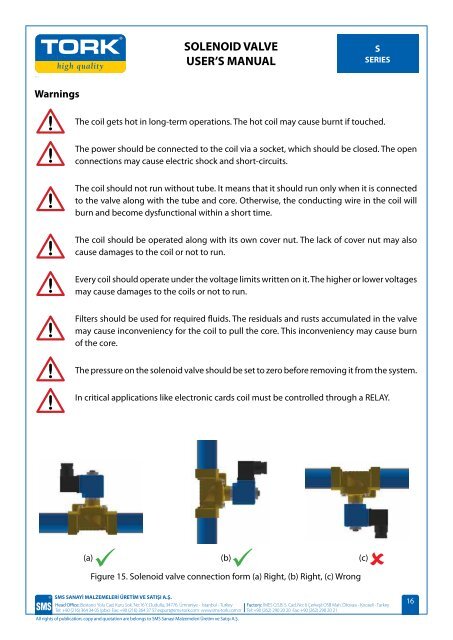
SOLENOID VALVEUSER’S MANUALSSERIESSOLENOID VALVEUSER’S MANUALSSERIESWarningsThe coil gets hot in long-term operations. The hot coil may cause burnt if touched.The power should be connected to the coil via a socket, which should be closed. The openconnections may cause electric shock and short-circuits.In solenoid <strong>valve</strong> assembly, please be careful that the coil should not be at the lower partwhen conducting assembly. Otherwise, the core in the hive shall be affected by the residualsand rusts accumulated in time and prevent the coil to move the core. The solenoid <strong>valve</strong>may be assembled as shown in Figure 15 a or Figure 15 b.A filter should be used, if there are particles in the fluid to be used.The coil should not run without tube. It means that it should run only when it is connectedto the <strong>valve</strong> along with the tube and core. Otherwise, the conducting wire in the coil willburn and become dysfunctional within a short time.EarthThe coil should be operated along with its own cover nut. The lack of cover nut may alsocause damages to the coil or not to run.21Every coil should operate under the voltage limits written on it. The higher or lower voltagesmay cause damages to the coils or not to run.Filters should be used for required fluids. The residuals and rusts accumulated in the <strong>valve</strong>may cause inconveniency for the coil to pull the core. This inconveniency may cause burnof the core.The pressure on the solenoid <strong>valve</strong> should be set to zero before removing it from the system.(a)(b)Figure 16.(a) Connector inner parts, (b) Connector connection pointsWhen connecting the cable ends to connector, for AC voltages, the phase-neutral ends, andfor the DC voltages, the positive (+) and negative (-) terminals should be connected to thenumber 1 and 2 connections. The earth terminal should be connected with the groundingconductor in the cable, if any. The grounding conductor is the yellow-green wireIn critical applications like electronic cards coil must be controlled through a RELAY.(a)(b)Figure 17. The position of the connecting cable (a) Right (b) Wrong(a) (b) (c)Figure 15. Solenoid <strong>valve</strong> connection form (a) Right, (b) Right, (c) WrongSMS SANAYİ MALZEMELERİ ÜRETİM VE SATIŞI A.Ş.Head Office: Bostancı Yolu Cad. Kuru Sok. No:16 Y. Dudullu, 34776 Ümraniye - İstanbul - TurkeyTel: +90 (216) 364 34 05 (pbx) Fax: +90 (216) 364 37 57 export@sms-tork.com www.sms-tork.com.trAll rights of publication, copy and quotation are belongs to SMS Sanayi Malzemeleri Üretim ve Satışı A.Ş.Factory: İMES O.S.B. 5. Cad. No: 6 Çerkeşli OSB Mah. Dilovası - Kocaeli - TurkeyTel: +90 (262) 290 20 20 Fax: +90 (262) 290 20 21Any bending or twisting should not be found with the cable connected to the connectorin order to avoid any deficits resulting from any loose contact or short-circuit due to anycrush. The cable should be uprights as shown in the Figure 17 a. In addition, the twists in theconnector input may allow humidity to penetrate into the connector. In order to preventhumidity or water to leak into the socket, the diameter of the cable should be in a size thatprovides sealing.SMS SANAYİ MALZEMELERİ ÜRETİM VE SATIŞI A.Ş.Head Office: Bostancı Yolu Cad. Kuru Sok. No:16 Y. Dudullu, 34776 Ümraniye - İstanbul - TurkeyTel: +90 (216) 364 34 05 (pbx) Fax: +90 (216) 364 37 57 export@sms-tork.com www.sms-tork.com.trAll rights of publication, copy and quotation are belongs to SMS Sanayi Malzemeleri Üretim ve Satışı A.Ş.16 17Factory: İMES O.S.B. 5. Cad. No: 6 Çerkeşli OSB Mah. Dilovası - Kocaeli - TurkeyTel: +90 (262) 290 20 20 Fax: +90 (262) 290 20 21