Table Of Contents Backflow Replacement Parts
BACKFLOW PARTS MANUAL.pdf - National Fire Equipment
BACKFLOW PARTS MANUAL.pdf - National Fire Equipment

You also want an ePaper? Increase the reach of your titles
YUMPU automatically turns print PDFs into web optimized ePapers that Google loves.
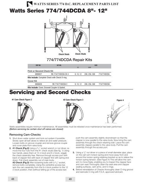
WATTS SERIES 774 D.C. REPLACEMENT PARTS LISTWatts Series 774/744DCDA 8"- 12"EDP NO KIT NO. SIZEin.mmCheck StudsCheck Studs0888827 RK 774/774DCDA CK 4 8, 10, 12 200, 250, 300 774/774DCDAKits include: Complete Check with Check O-ring.0888828 RK 774/774DCDA C 8, 10, 12 200, 250, 300 774/774DCDAKits include: Cover, Grooved Coupler & Gasket.Servicing and Second Checks#1 Cam-Check Figure 2 #2 Cam-Check Figure 3 Figure 4Watts assemblies require minimum maintenance. All assemblies must be retested once maintenance has been performed.(Before servicing be certain shut off valves are closed)1. Shut down water system and lock out system if possible.Slowly open all ball valves to relieve air and water pressure.Loosen bolts on groove coupler and remove groove coupleand cover plate from valve body2. #1 Check (Fig.2) Using a 9 ⁄ 16 " socket wrench or nut driver, removethe four nuts from the #1 check studs (See fig. 1) Usingtwo hands, place them at 12 o'clock and 6 o'clock, wigglethe check assembly free. Remove through access port withback of clapper first with back of clapper first with spring enddown. Pull check assembly out of main body.#2 Check (Fig.3) After loosening bolts with a 9 ⁄ 16 " socket,remove bolts completely, Using the centerline access bar,spin the cam assembly from the 9 o'clock position to the 12o'clock position, then (without letting go of the access bar)push the cam assembly slightly downstream so that theclapper is now parallel to the valve body. Now bring the camassembly through the check retaining wall. Leave the camassembly clapper parallel to the valve body. Pull the camassembly through the access port.3. Using a 3 ⁄ 8 " nut driver or a piece of small diameter pipe, placeon the cam arm torsion spring and move away from andaround the torsion spring retaining bracket so as to relieve thetorsion spring tension. (See Figure 4) This will allow the camarm to move freely, enabling you to inspect the clapper faceand cam seat.Thoroughly clean the seat area and clappersealing surfaces, cam arms, and O-rings.4. Before reinstallation of Checks thoroughly clean O-ring grooveand lubricate O-ring with F.D.A. approved lubricant.6 48 48