interpolation-IC
EBI7901CAx-DA-UF Incremental Sensor Module - Sensitec
EBI7901CAx-DA-UF Incremental Sensor Module - Sensitec
- No tags were found...

You also want an ePaper? Increase the reach of your titles
YUMPU automatically turns print PDFs into web optimized ePapers that Google loves.
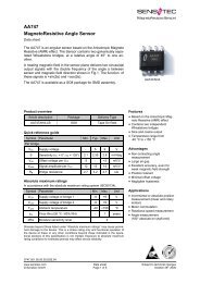
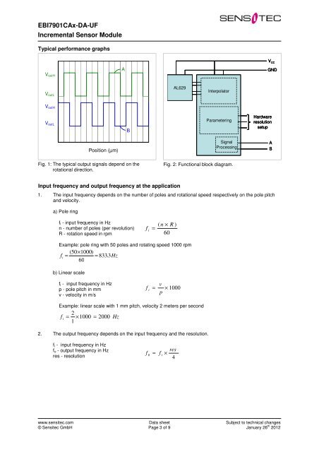
EBI7901CAx-DA-UFIncremental Sensor ModuleTypical performance graphs6,5V CCError (deg)6V outH5,5V outL5AAL629InterpolatorGNDV outH4,54V outL3,5BParameteringHardwareresolutionsetup3Position (µm)SignalProcessingABFig. 1: The typical output signals depend on therotational direction.Fig. 2: Functional block diagram.Input frequency and output frequency at the application1. The input frequency depends on the number of poles and rotational speed respectively on the pole pitchand velocity.a) Pole ringf i - input frequency in Hzn - number of poles (per revolution)R - rotation speed in rpm( n × R )f i=60Example: pole ring with 50 poles and rotating speed 1000 rpm(50×1000)f i= = 833. 3Hz60b) Linear scalef i - input frequency in Hzp - pole pitch in mmv - velocity in m/sf i= pv× 1000Example: linear scale with 1 mm pitch, velocity 2 meters per second2f i= × 1000 = 2000 Hz12. The output frequency depends on the input frequency and the resolution.f i - input frequency in Hzf o - output frequency in Hzres - resolutionf = fi×0res4www.sensitec.com© Sensitec GmbHData sheetPage 3 of 9Subject to technical changesJanuary 26 th 2012