As
Efficiency of a skeletonized distal jet appliance supported by ...
Efficiency of a skeletonized distal jet appliance supported by ...

Create successful ePaper yourself
Turn your PDF publications into a flip-book with our unique Google optimized e-Paper software.
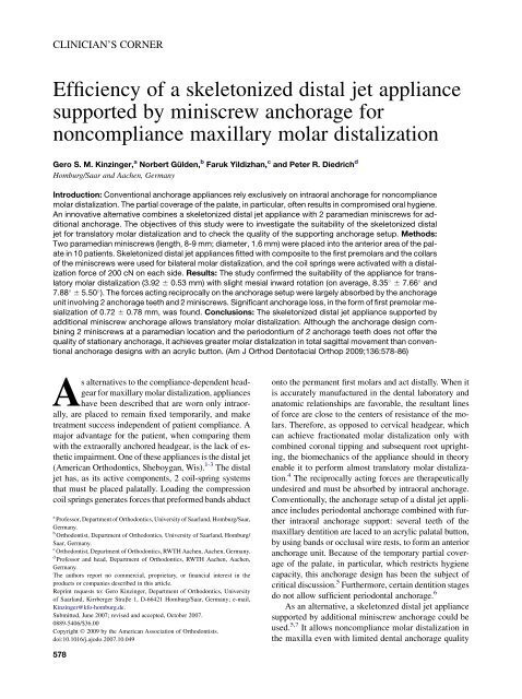
CLINICIAN’S CORNER<br />
Efficiency of a skeletonized distal jet appliance<br />
supported by miniscrew anchorage for<br />
noncompliance maxillary molar distalization<br />
Gero S. M. Kinzinger, a Norbert Gülden, b Faruk Yildizhan, c and Peter R. Diedrich d<br />
Homburg/Saar and Aachen, Germany<br />
Introduction: Conventional anchorage appliances rely exclusively on intraoral anchorage for noncompliance<br />
molar distalization. The partial coverage of the palate, in particular, often results in compromised oral hygiene.<br />
An innovative alternative combines a skeletonized distal jet appliance with 2 paramedian miniscrews for additional<br />
anchorage. The objectives of this study were to investigate the suitability of the skeletonized distal<br />
jet for translatory molar distalization and to check the quality of the supporting anchorage setup. Methods:<br />
Two paramedian miniscrews (length, 8-9 mm; diameter, 1.6 mm) were placed into the anterior area of the palate<br />
in 10 patients. Skeletonized distal jet appliances fitted with composite to the first premolars and the collars<br />
of the miniscrews were used for bilateral molar distalization, and the coil springs were activated with a distalization<br />
force of 200 cN on each side. Results: The study confirmed the suitability of the appliance for translatory<br />
molar distalization (3.92 6 0.53 mm) with slight mesial inward rotation (on average, 8.35 6 7.66 and<br />
7.88 6 5.50 ). The forces acting reciprocally on the anchorage setup were largely absorbed by the anchorage<br />
unit involving 2 anchorage teeth and 2 miniscrews. Significant anchorage loss, in the form of first premolar mesialization<br />
of 0.72 6 0.78 mm, was found. Conclusions: The skeletonized distal jet appliance supported by<br />
additional miniscrew anchorage allows translatory molar distalization. Although the anchorage design combining<br />
2 miniscrews at a paramedian location and the periodontium of 2 anchorage teeth does not offer the<br />
quality of stationary anchorage, it achieves greater molar distalization in total sagittal movement than conventional<br />
anchorage designs with an acrylic button. (Am J Orthod Dentofacial Orthop 2009;136:578-86)<br />
<strong>As</strong> alternatives to the compliance-dependent headgear<br />
for maxillary molar distalization, appliances<br />
have been described that are worn only intraorally,<br />
are placed to remain fixed temporarily, and make<br />
treatment success independent of patient compliance. A<br />
major advantage for the patient, when comparing them<br />
with the extraorally anchored headgear, is the lack of esthetic<br />
impairment. One of these appliances is the distal jet<br />
(American Orthodontics, Sheboygan, Wis). 1-3 The distal<br />
jet has, as its active components, 2 coil-spring systems<br />
that must be placed palatally. Loading the compression<br />
coil springs generates forces that preformed bands abduct<br />
a Professor, Department of Orthodontics, University of Saarland, Homburg/Saar,<br />
Germany.<br />
b Orthodontist, Department of Orthodontics, University of Saarland, Homburg/<br />
Saar, Germany.<br />
c Orthodontist, Department of Orthodontics, RWTH Aachen, Aachen, Germany.<br />
d Professor and head, Department of Orthodontics, RWTH Aachen, Aachen,<br />
Germany.<br />
The authors report no commercial, proprietary, or financial interest in the<br />
products or companies described in this article.<br />
Reprint requests to: Gero Kinzinger, Department of Orthodontics, University<br />
of Saarland, Kirrberger Strabe 1, D-66421 Homburg/Saar, Germany; e-mail,<br />
Kinzinger@kfo-homburg.de.<br />
Submitted, June 2007; revised and accepted, October 2007.<br />
0889-5406/$36.00<br />
Copyright Ó 2009 by the American <strong>As</strong>sociation of Orthodontists.<br />
doi:10.1016/j.ajodo.2007.10.049<br />
onto the permanent first molars and act distally. When it<br />
is accurately manufactured in the dental laboratory and<br />
anatomic relationships are favorable, the resultant lines<br />
of force are close to the centers of resistance of the molars.<br />
Therefore, as opposed to cervical headgear, which<br />
can achieve fractionated molar distalization only with<br />
combined coronal tipping and subsequent root uprighting,<br />
the biomechanics of the appliance should in theory<br />
enable it to perform almost translatory molar distalization.<br />
4 The reciprocally acting forces are therapeutically<br />
undesired and must be absorbed by intraoral anchorage.<br />
Conventionally, the anchorage setup of a distal jet appliance<br />
includes periodontal anchorage combined with further<br />
intraoral anchorage support: several teeth of the<br />
maxillary dentition are laced to an acrylic palatal button,<br />
by using bands or occlusal wire rests, to form an anterior<br />
anchorage unit. Because of the temporary partial coverage<br />
of the palate, in particular, which restricts hygiene<br />
capacity, this anchorage design has been the subject of<br />
critical discussion. 5 Furthermore, certain dentition stages<br />
do not allow sufficient periodontal anchorage. 6<br />
<strong>As</strong> an alternative, a skeletonzed distal jet appliance<br />
supported by additional miniscrew anchorage could be<br />
used. 5,7 It allows noncompliance molar distalization in<br />
the maxilla even with limited dental anchorage quality<br />
578
American Journal of Orthodontics and Dentofacial Orthopedics Kinzinger et al 579<br />
Volume 136, Number 4<br />
and, by dispensing with an acrylic button, also achieves<br />
better hygiene of the palatal mucosa.<br />
In an in-vitro study, Kinzinger and Diedrich 4 demonstrated<br />
that the distal jet coil-spring systems allowed<br />
almost translatory tooth movement in the sagittal plane<br />
with uprighting effects on the dental root over a simulated<br />
distalization section of 3 mm based on a constant<br />
distalization force of 200 cN, combined with a mesial<br />
tipping moment. In the transverse plane, a force constantly<br />
directed toward the buccal aspect and a mesially<br />
rotating moment resulted in combined buccal movement<br />
and therapeutically undesired mesial and inward<br />
rotation of the permanent first molar.<br />
The aims of this in-vivo study were to investigate<br />
clinically the efficiency of the skeletonized distal jet<br />
supported by additional miniscrew anchorage and to<br />
compare the outcomes with the in-vitro series of measurements.<br />
A review of the literature resulted in a discussion<br />
of the share of anchorage loss in the total<br />
movement in the sagittal plane, hence of the quality of<br />
the miniscrew-supported periodontal anchorage setup,<br />
when comparing it with other conventional intraorally<br />
anchored, noncompliance distalization appliances.<br />
MATERIAL AND METHODS<br />
A skeletonized distal jet appliance was placed for bilateral<br />
molar distalization in the maxilla in 10 patients<br />
(8 girls, 2 boys; average age, 12 years 1 month) with<br />
dentoalveolar Class II malocclusion and dental archlength<br />
discrepancies. The mean treatment duration<br />
was 6.7 months. Of the total of 20 second molars, 11<br />
were germinating, and 5 were erupting. Only 4 had<br />
already reached the occlusal plane.<br />
For the distal jet used in this study, the palatal acrylic<br />
button was removed as a means of anchorage. Instead, the<br />
modified appliance was anchored skeletally to 2 miniscrews<br />
placed into the palate at a paramedian location<br />
and, additionally, dentally to 2 occlusal rests. In terms<br />
of laboratory technique, this meant that prefabricated telescope<br />
spring assemblies, whose wings were bent distally<br />
to form occlusal rests, were connected to each other by using<br />
a soldered or laser-welded transverse wire (Fig 1).<br />
Every patient’s bone supply in the anterior area of the<br />
palate was analyzed on lateral cephalographs to determine<br />
the length of the screw shaft. After a preoperative<br />
mouth rinse with 0.1% chlorhexidine gluconate solution<br />
and local terminal anesthesia with an adrenalin-free<br />
anesthetic, 2 miniscrews with neck and collar (length,<br />
8-9 mm, diameter, 1.6 mm; Forestadent, Pforzheim,<br />
Germany; or System Dual Top, Jeil Medical Corporation,<br />
Seoul, South Korea) were placed at a paramedian location<br />
in the anterior area of the palate (at the line of the first<br />
Fig 1. Skeletonized distal jet appliance supported by<br />
additional miniscrew anchorage: treatment of a girl<br />
aged 11 years 1 month; duration of distal jet treatment,<br />
5 months. A, Occlusal view immediately after skeletonized<br />
distal jet placement: in terms of laboratory technique,<br />
prefabricated coil-telescope systems, the wings<br />
of which are bent distally to form occlusal rests, are connected<br />
to each other with a wire soldered to them. This<br />
transverse connecting wire is fitted dorsally to the miniscrew<br />
necks. B, Occlusal view after molar distalization:<br />
clinical assessment shows bodily molar distalization<br />
and spontaneous second premolar dental drifting.<br />
premolars) with a manual screwdriver and adequate<br />
sodium chloride cooling. No predrilling was performed.<br />
All miniscrews were tested for primary stability by using<br />
a probe; they were loaded a week after placement.<br />
Skeletonized distal jet appliances were attached to the<br />
premolars by using occlusal wire rests and to the necks of<br />
the miniscrews with transverse wires fitted dorsally and<br />
secured with composite. The occlusal rests also resulted<br />
in transverse reinforcement of the appliances. Accordingly,<br />
the anchorage setup consisted of a periodontal
580 Kinzinger et al American Journal of Orthodontics and Dentofacial Orthopedics<br />
October 2009<br />
UR2<br />
UL2<br />
A<br />
N<br />
S<br />
ANS-PNS´<br />
UR6<br />
mb<br />
cf<br />
db<br />
UL6<br />
Ar<br />
PNS<br />
A<br />
ANS<br />
Go-Me´<br />
MPR<br />
Fig 2. Cast analysis (changes in the horizontal plane):<br />
angular and linear measurements to determine changes<br />
in the transverse width of the dental arch and rotation of<br />
the first molars.<br />
Go<br />
B<br />
footing with the added support of miniscrews. The wings<br />
of the arc sections, which represent a bayonet bend, were<br />
fitted into the palatal sheaths of the molar bands. Then the<br />
loaded coil systems, with superelastic compression<br />
springs, were activated by fitting attachment screws dorsally<br />
with a distalization force of 200 cN for each system<br />
and reactivated every 4 weeks.<br />
To verify molar movement in the horizontal plane,<br />
plaster dental casts were taken at the start of treatment<br />
(T1) and after distal jet appliance removal (T2). The<br />
changes near the molars were assessed by measuring<br />
corresponding casts with a digital sliding caliper. Objects<br />
of analysis were changes in length of the supporting<br />
zone, increase or decrease of the transverse width of the<br />
dental arch at the line of the first molars, and extent and<br />
kind of tooth rotation. For every cast, the distance from<br />
the distal point of contact of the lateral incisor to the mesial<br />
point of contact of the first molar and, bilaterally, the<br />
distance from the lowest point of the central fossa to the<br />
mesiobuccal and the distobuccal cusps of the first molar<br />
were registered. In addition, the angles between a line<br />
running through the mesiobuccal and distobuccal cusps<br />
and the midpalatal raphe were measured (Fig 2).<br />
The cephalographs taken at T1 and T2 were analyzed<br />
to determine changes in the following parameters (Fig 3).<br />
1. SNA: the angle between the anterior cranial base<br />
and the deepest point of the ventral concavity of<br />
the maxilla.<br />
2. SNB: the angle between the anterior cranial base<br />
and the deepest point of the ventral concavity of<br />
the mandible.<br />
3. S-N/ANS-PNS: the angle between the anterior<br />
cranial base and the palatal plane.<br />
B<br />
P<br />
S<br />
Pt<br />
PNS<br />
4. ANS-PNS/Go-Me: the angle between the palatal<br />
plane and the mandibular plane.<br />
5. Björk’s summation angle: the sum of the saddle<br />
angle (NSAr), the articular angle (SArGo), and<br />
the gonial angle (ArGoMe).<br />
Me<br />
Or<br />
N<br />
ANS<br />
Fig 3. Cephalometric analysis (changes in the sagittal<br />
plane): angles and distances registered on the lateral<br />
cephalograph before and after molar distalization: A,<br />
skeletal angular and linear values; B, dental angular<br />
and linear values.
American Journal of Orthodontics and Dentofacial Orthopedics Kinzinger et al 581<br />
Volume 136, Number 4<br />
6. S-Go:N-Me: the facial height ratio (posterior face<br />
height to anterior face height).<br />
7. U1-CEJ/PTV: the distance from the maxillary<br />
central incisor to the pterygoid vertical.<br />
8. U4-CEJ/PTV: the distance from the maxillary first<br />
premolar to the pterygoid vertical.<br />
9. U5-CEJ/PTV, the distance from the maxillary second<br />
premolar to the pterygoid vertical.<br />
10. U6-CEJ/PTV: the distance from the maxillary first<br />
molar to the pterygoid vertical.<br />
11. U1/ANS-PNS: the angle between the maxillary<br />
central incisor and the palatal plane.<br />
12. U1/SN: the angle between the maxillary central<br />
incisor and the anterior cranial base.<br />
13. U4/ANS-PNS: the angle between the maxillary<br />
first premolar and the palatal plane.<br />
14. U4/SN: the angle between the maxillary first premolar<br />
and the anterior cranial base.<br />
15. U5/ANS-PNS: the angle between the maxillary<br />
second premolar and the palatal plane.<br />
16. U5/SN: the angle between the maxillary second<br />
premolar and the anterior cranial base.<br />
17. U6/ANS-PNS: the angle between the maxillary<br />
first molar and the palatal plane.<br />
18. U6/SN: the angle between the maxillary first<br />
molar and the anterior cranial base.<br />
19. U1-CEJ/ANS-PNS: the distance from the maxillary<br />
central incisor to the palatal plane.<br />
20. U4-CEJ/ANS-PNS, the distance from the maxillary<br />
first premolar to the palatal plane.<br />
21. U5-CEJ/ANS-PNS: the distance from the maxillary<br />
second premolar to the palatal plane.<br />
22. U6-CEJ/ANS-PNS: the distance from the maxillary<br />
first molar to the palatal plane.<br />
SNA, SNB, S-N/ANS-PNS, ANS-PNS/Go-Me,<br />
Björk’s summation angle, and the facial height ratio<br />
were measured or computed to verify any skeletal<br />
changes.<br />
In the sagittal plane, the relative incisor and first premolar<br />
mesial movement, hence the anchorage loss, and<br />
the relative second premolar and first molar distal movement<br />
in relation to the pterygoid vertical (U1-CEJ/PTV,<br />
U4-CEJ/PTV, U5-CEJ/PTV, and U6-CEJ/PTV) were<br />
determined. The respective points of reference for the<br />
measurements were the cementoenamel junction<br />
(CEJ) on the longitudinal axis of the teeth. Growthinduced<br />
changes (increase of 1 mm per year) were taken<br />
into account.<br />
The amounts of labial tipping of the incisors and<br />
first premolars and distal tipping of the second premolars<br />
and first molars were determined based on the<br />
angles between the longitudinal tooth axis and, respectively,<br />
the palatal plane or the anterior cranial base (U1/<br />
ANS-PNS, U1/SN; U4/ANS-PNS, U4/SN; U5/ANS-<br />
PNS, U5/SN; U6/ANS-PNS, U6/SN).<br />
Potential tooth intrusions and extrusions were verified<br />
in the palatal plane (U1-CEJ/ANS-PNS, U4-CEJ/<br />
ANS-PNS, U5-CEJ/ANS-PNS, and U6-CEJ/ANS-<br />
PNS).<br />
Statistical analysis<br />
Statistical computations were performed with SPSS<br />
software (version 14, SPSS, Chicago, Ill). Casts and lateral<br />
cephalographs were traced twice at a 4-week interval.<br />
If values deviated, the means of both measurements<br />
were fed into the statistical analysis. Then the arithmetic<br />
mean and the standard deviation were computed for every<br />
variable used in the in-vivo measurements, and the<br />
changes of each variable from T1 to T2 were statistically<br />
analyzed with a 1-sample t test. Thereby, we determined<br />
which effective changes were therapeutically<br />
induced by the treatment as evidence against the null<br />
hypothesis. Differences with a probability of error less<br />
than 5% (P \0.05) were considered statistically significant.<br />
RESULTS<br />
Metrical assessment of the maxilla casts before and<br />
after molar distalization with a skeletonized distal jet<br />
appliance showed the following dental position changes<br />
of the permanent first molars (Table I).<br />
The supporting zones increased by 4.01 6 0.63 mm<br />
in the first quadrant and 3.64 6 0.69 mm in the second<br />
quadrant. The transverse widths of the dental arch increased<br />
by means of 1.79 6 1.08 mm between the mesiobuccal<br />
cusps, 2.58 6 0.69 mm between the central<br />
fossae, and 3.03 6 0.68 mm between the distobuccal<br />
cusps; this indicates both expansion and mesial inward<br />
rotation of the permanent first molars. When we looked<br />
more closely, the permanent first molars of the first<br />
quadrant had rotated mesiopalatally and distobuccally<br />
by a mean 8.35 6 7.66 and those of the second quadrant,<br />
by 7.88 6 5.50 . All position changes of the<br />
permanent first molars were significant.<br />
Skeletal assessments showed that the cranial base<br />
remained constant, with changes of the SNA angle of<br />
only a mean 0.19 6 0.80 and the SNB angle of only<br />
a mean 0.13 6 0.82 . The positional relationships of<br />
the palatal plane to the anterior cranial base and to the<br />
mandibular plane were virtually unchanged. Björk’s<br />
summation angle changed by only 0.73 6 1.26 during<br />
molar distalization, and the facial height ratio changed<br />
by 0.58% 6 1.51%. All registered skeletal changes<br />
during treatment were not significant (Table II).
582 Kinzinger et al American Journal of Orthodontics and Dentofacial Orthopedics<br />
October 2009<br />
Table I. Changes in permanent first molar position induced by distal jet therapy in the horizontal plane<br />
Cast analysis n T1 mean T1 SD T2 mean T2 SD DT1-T2 mean DT1-T2 SD Significance<br />
UR2 distal-UR6 mesial (mm) 10 20.80 2.04 24.81 2.34 –4.01 0.63<br />
UL2 distal-UL6 mesial (mm) 10 21.17 1.90 24.81 2.08 –3.64 0.69<br />
‡<br />
Mesiobuccal cusp tips UR6-UL6 (mm) 10 50.80 2.16 52.59 1.28 –1.79 1.08<br />
†<br />
Central fossa UR6-UL6 (mm) 10 45.80 2.36 48.39 2.04 –2.58 0.69<br />
‡<br />
Distobuccal cusp tips UR6-UL6 (mm) 10 53.06 1.70 56.09 1.49 –3.03 0.68<br />
‡<br />
Tooth UR6 rotation ( ) 10 12.86 6.15 21.21 6.28 –8.35 7.66 *<br />
Tooth UL6 rotation ( ) 10 13.43 4.29 18.93 5.94 –7.88 5.50 *<br />
Determination of type of molar rotation: angle between midpalatal raphe and a line running through the mesiobuccal and distobuccal cusps of the<br />
molars; for DT1-T2 (value before distalization) – (value after distalization): positive value 5 mesiobuccal and distopalatal rotation, negative value 5<br />
mesiopalatal or distobuccal rotation.<br />
*P \0.05; † P \0.01; ‡ P \0.001.<br />
‡<br />
Table II. Skeletal angular and linear measurements<br />
Cephalometric analysis n T1 mean T1 SD T2 mean T2 SD D T1-T2 mean D T1-T2 SD Significance<br />
Skeletal-angular<br />
SNA ( ) 10 83.55 2.63 83.36 2.78 0.19 0.80 NS<br />
SNB ( ) 10 79.83 3.42 79.70 3.27 0.13 0.83 NS<br />
S-N/ANS-PNS ( ) 10 5.56 1.92 5.18 1.53 0.38 1.18 NS<br />
ANS-PNS/Go-Me ( ) 10 24.20 4.31 25.08 4.14 –0.88 1.09 NS<br />
Björk’s summation angle ( ) 10 389.61 3.29 390.34 3.49 –0.73 1.26 NS<br />
Skeletal-linear<br />
S-Go:N-Me (%) 10 67.49 2.79 66.91 2.60 0.58 1.51 NS<br />
NS, Not significant.<br />
In the area of the CEJ, the permanent first molars<br />
were distalized by a mean of 3.92 6 0.53 mm and intruded<br />
by a mean of 0.16 6 0.26 mm. At the same<br />
time, they experienced distal tipping of 2.79 6 2.51 <br />
in relation to the palatal plane and 3.00 6 2.31 in relation<br />
to the anterior cranial base. The second premolars,<br />
which were not part of the anchorage setup, drifted distally<br />
after the molars by 1.87 6 0.74 mm, elongating by<br />
0.42 6 0.41 mm and tipping, in relation to the respective<br />
reference planes, by 3.00 6 2.69 and 3.21 6 2.86 .<br />
The first premolars, included in the anchorage setup,<br />
mesialized by 0.72 6 0.78 mm, extruded by 0.14 6 0.14<br />
mm, and, at the same time, tipped by 1.15 6 2.98 in<br />
relation to the palatal plane and by 0.79 6 2.23 in relation<br />
to the anterior cranial base. The central incisors<br />
were protruded by 0.36 6 0.32 mm and extruded by<br />
0.14 6 0.29 mm, and showed slight labial tipping<br />
of 0.57 6 0.79 in relation to the palatal plane and<br />
0.64 6 0.75 to the anterior cranial base.<br />
All linear dental movements in relation to the pterygoid<br />
vertical, the extrusion of the premolars, and the<br />
angular dental position changes of the second premolars<br />
and first molars were significant (Table III).<br />
The total movement in the sagittal plane was 4.28 6<br />
0.51 mm (cumulating molar distalization and central incisor<br />
protrusion) or 4.64 6 1.06 mm (cumulating molar<br />
distalization and first premolar mesialization). Based on<br />
the values obtained for the permanent first molars—<br />
distalization length of a mean 3.92 6 0.53 mm—molar<br />
distalization represents 91.71% 6 7.32% and 86.56%<br />
6 13.21%, respectively, of the total sagittal movement<br />
(Table IV).<br />
DISCUSSION<br />
The outcomes confirm the efficiency of the distal jet<br />
in clinical applications. Cast registrations showed that<br />
the supporting zone had increased, and that a therapeutically<br />
desired widening of the dental arch, as well as mesial<br />
inward and distal outward rotations of the molars,<br />
had occurred. The biomechanical explanation of this effect<br />
is that force is applied palatally from the center of<br />
resistance of the molars. In theory, a toe-in bend would<br />
be appropriate to compensate for this effect, but it results<br />
in friction in the guide tubes of the appliance.<br />
This effect was verified with the casts used and by an<br />
in-vitro registration. The resultant adhesive effect expressing<br />
this friction reduced the distalization force substantially<br />
and, accordingly, would be an obstacle for<br />
distalization of the molars. Therefore, a toe-in bend<br />
should not be used, although it would be therapeutically<br />
desirable. 4 After the distal jet treatment, the molars
American Journal of Orthodontics and Dentofacial Orthopedics Kinzinger et al 583<br />
Volume 136, Number 4<br />
Table III. Dental angular and linear measurements<br />
Cephalometric analysis n T1 mean T1 SD T2 M T2 SD D T1-T2 M D T1-T2 SD Significance<br />
Dental-angular<br />
U1/AN-PNS ( ) 10 107.93 4.80 108.50 4.94 –0.57 0.79 NS<br />
U1/SN ( ) 10 101.86 5.28 102.50 5.45 –0.64 0.75 NS<br />
U4/AN-PNS ( ) 10 91.86 6.01 90.71 6.11 1.15 2.98 NS<br />
U4/SN ( ) 10 85.86 7.61 85.07 7.37 0.79 2.23 NS<br />
U5/ANS-PNS ( ) 10 82.29 4.71 79.29 5.62 3.00 2.69 *<br />
U5/SN ( ) 10 76.50 5.37 73.29 5.26 3.21 2.86 *<br />
U6/ANS-PNS ( ) 10 75.36 3.82 72.57 4.04 2.79 2.51 *<br />
U6/SN ( ) 10 69.71 4.79 66.71 4.35 3.00 2.31 *<br />
Dental-linear<br />
U1-CEJ/PTV (mm) 10 52.54 2.94 52.90 2.98 –0.36 0.32 *<br />
U4-CEJ/PTV (mm) 10 38.47 3.37 39.19 3.78 –0.72 0.78 *<br />
U5-CEJ/PTV (mm) 10 31.21 3.11 29.34 3.00 1.87 0.74<br />
†<br />
U6-CEJ/PTV (mm) 10 22.59 3.31 18.67 3.11 3.92 0.53<br />
‡<br />
U1-CEJ/ANS-PNS (mm) 10 17.96 2.62 18.10 2.44 –0.14 0.29 NS<br />
U4-CEJ/ANS-PNS (mm) 10 15.79 1.53 15.93 1.55 –0.14 0.14 *<br />
U5-CEJ/ANS-PNS (mm) 10 14.59 2.06 15.01 1.97 –0.42 0.41 *<br />
U6-CEJ/ANS-PNS (mm) 10 13.16 1.78 13.00 1.65 0.16 0.26 NS<br />
*P \0.05; † P \0.01; ‡ P \0.001; NS, not significant.<br />
Table IV. Proportion of maxillary molar distalization in<br />
total movement in the sagittal plane<br />
Cephalometric analysis n D T1-T2 mean D T1-T2 SD<br />
Dental-linear (mm)<br />
U1-CEJ/PTV (mm) 10 –0.36 0.32<br />
U4-CEJ/PTV (mm) 10 –0.72 0.78<br />
U6-CEJ/PTV (mm) 10 3.92 0.53<br />
Total sagittal movement 1-6* 10 4.28 0.51<br />
Total sagittal movement 4-6 † 10 4.64 1.06<br />
Calculation of ratio (%)<br />
Proportion of molar 10 91.71 7.32<br />
sagittal movement 1-6 ‡<br />
distalization in total<br />
Proportion of molar<br />
distalization in total<br />
sagittal movement 4-6 § 10 86.56 13.21<br />
*Total movement in the sagittal plane 1-6 5 [U1-CEJ/PTV] 1 [U6-<br />
CEJ/PTV]; † Total movement in the sagittal plane 4-6 5 [U4-CEJ/<br />
PTV] 1 [U6-CEJ/PTV]; ‡ Calculation: proportion of molar distalization<br />
in total sagittal movement 1-6 5 100 3 (U6-CEJ/PTV)/([U1-<br />
CEJ/PTV] 1 [U6-CEJ/PTV]); § Calculation: proportion of molar distalization<br />
in total sagittal movement 4-6 5 100 3 (U6-CEJ/PTV)/<br />
([U4-CEJ/PTV] 1 [U6-CEJ/PTV]).<br />
should be derotated with an appropriate appliance, such<br />
as a transpalatal bar or a bi-helix.<br />
We found, during lateral cephalograph analysis, unlike<br />
the results of the in-vitro analysis, that the permanent<br />
first molars experienced slight dental crown<br />
tipping in the sagittal plane rather than root uprighting. 4<br />
The cause of this might be that the patients’ palatal<br />
vaults were not deep enough to enable placement of<br />
the loaded coil systems at the level of the center of resistance<br />
of the molars. Also, the location of the center of<br />
resistance can be determined only by approximation.<br />
Moreover, the respective development stages of the second<br />
molars might influence the extent of distal tipping<br />
of the first molars. In most patients in this study, the second<br />
molars were germinating or erupting. In a clinical<br />
study with pendulum appliances, Kinzinger et al 8<br />
showed that the extent of distal tipping is relatively<br />
greater when the second molars are only germinating.<br />
This phenomenon can be explained as follows: a germinating<br />
second molar has the same effect as a lever pivot<br />
point on the permanent first molar to be distalized; the<br />
first molar, when reacting to distalization, tips over the<br />
second molar germ. <strong>As</strong> its root is developing and the<br />
permanent second molar is erupting, the point of contact<br />
between the 2 molars gradually moves coronally. The<br />
tendency for the first molar to tip thereby decreases.<br />
Conventionally, the anchorage setup of exclusively<br />
intraorally anchored appliances for noncompliance molar<br />
distalization combines an acrylic button on the palatal<br />
mucosa with using the periodontium of anchorage<br />
teeth. The disadvantages of this kind of anchorage include,<br />
in particular, restrictions to hygiene 5 and contraindications<br />
based on certain dentition stages and local<br />
situations. 7 Moreover, it must be discussed how far<br />
the anchorage effect of an anteriorly placed Nance<br />
button potentially relies only on hydrodynamic interactions<br />
due to the resilient mucosa. Thereby it would be<br />
a disqualifying design for stationary anchorage designs,<br />
and hence must not be overestimated in terms of anchorage<br />
quality. 5
584 Kinzinger et al American Journal of Orthodontics and Dentofacial Orthopedics<br />
October 2009<br />
Table V. Studies using different conventionally intraorally anchored appliances for maxillary molar distalization<br />
Author/reference<br />
Distalization appliance<br />
Treatment Soft-tissue<br />
subjects (n) support* Dental anchorage †<br />
Share of molar<br />
distalization in total<br />
movement (%)<br />
Angelieri et al 31 Hilgers pendulum with uprighting activation 22 NP 2 B PM1 35.7 PM1, 45.4 I<br />
2 OW PM2<br />
Bolla et al 32 Distal jet 20 NP 2 B PM1 71.1 PM1<br />
Bondemark and Kurol 33 Magnets 10/10 NP 2 B PM2 70 I<br />
Bondemark et al 34 Magnets/supercoils 18/18 NP 2 B PM2 53.7 I/62.7 I<br />
Bondemark and Kurol 35 Magnets/supercoils 18/18 NP 2 B PM2 55 I/59 I<br />
Bondemark 36 Magnets/NiTi coils 21/21 NP 2 B PM2 59.1 PM1,<br />
57.8 I/67.6 PM1, 61.9 I<br />
Brickman et al 37 Jones jig 72 NP 2 B PM2 55.7 PM1<br />
Bussick and McNamara 38 Hilgers pendulum 101 NP 4 OW 76.0 PM1<br />
Byloff and Darendeliler 39 Hilgers pendulum 13 NP 4 OW 70.9 PM1<br />
Byloff et al 40<br />
Hilgers pendulum with<br />
20 NP 4 OW 64.2 PM1<br />
uprighting activation<br />
Chaques-<strong>As</strong>ensi and Kalra 41 Hilgers pendulum 26 NP 2 B PM1 70.6 PM1; 71.8 I<br />
Chiu et al 42 Distal jet/Hilgers pendulum 32/32 NP 2 B PM2/4 OW 51.8 PM1/81.3 PM<br />
Fortini et al 43 FCA 17 NP 2 B PM2 70.2 PM1; 76.9 I<br />
Fuziy et al 44 Hilgers pendulum 31 NP 2 B PM1 63.5 PM1<br />
2 OW PM2<br />
Gosh and Nanda 45 Hilgers pendulum 41 NP 4 OW 56.9 PM1<br />
Gulati et al 46 Jones jig 10 NP 4 B PM1 and PM2 55.0 PM1<br />
Haydar and Üner 47 Jones jig 10 NP 2 B PM2 45.0 PM1<br />
Joseph and Butchart 48 Hilgers pendulum 7 NP 4 OW 57.9 I<br />
Kinzinger et al 50 Pendulum K 50 NP 4 OW 72.5 I<br />
Kinzinger et al 8 Pendulum K 36 NP 4 OW 70.2 I<br />
Kinzinger et al 50 Pendulum K 30 NP 4 OW 76.3 PM1; 74.2 I<br />
Kinzinger et al 51 Pendulum K 10 NP 4 OW 73.5 I<br />
Mavropoulos et al 52 Jones jig 66 NP 2 B PM2 47.8 PM2; 51.3 I<br />
Ngantung et al 53 Distal jet 33 NP 2 B PM2 44.9 PM2<br />
Nishii et al 54 Distal jet 15 NP 2 B PM2 63.1 PM1; 61.5 I<br />
Papadopoulos et al 55 Modified jig 14 NP 2 B PM2 35 PM1, 37.8 I<br />
NiTi, Nickel-titanium; FCA, first-class appliance.<br />
* Intraoral anchorage designs: NP, Nance pad; B, premolar bands anchored to the Nance pad with connecting wires; OW, occlusal wire rests anchored<br />
to the Nance pad; PM1, first premolars; PM2, second premolars.<br />
† With specific reference: PM1, first premolar; PM2, second premolar; I, central incisor.<br />
Alternative anchorage components for molar distalization<br />
appliances include titanium miniscrews of small<br />
diameter and orthodontic implants of short length. In<br />
clinical application, short endosseous titanium implants<br />
provide quality stationary anchorage. 9-13 So-called miniscrews,<br />
placed at a location paramedian to the palatal<br />
suture in the patients in this study, are less costly and,<br />
compared with short implants, can be placeed and removed<br />
with minimal invasion.<br />
Most clinical and experimental studies as well as<br />
case reports on anchorage with miniscrews deal with<br />
primary stability, rate of loss, and patient comfort of<br />
these implants. 14-27 Only a few studies provide information<br />
on position stability of these anchorage components<br />
during orthodontic treatment. Liou et al 28 and Kinzinger<br />
et al 29 examined the anchorage quality of miniscrews<br />
subjected to orthodontic forces and concluded that,<br />
although they allowed stable anchorage, they did not<br />
fully maintain their positions under continuous loading.<br />
According to Park et al, 30 some mobility in orthodontic<br />
screw implants does not necessarily mean that the outcome<br />
is compromised. Rather, even minimally mobile<br />
miniscrews can provide sufficient anchorage quality.<br />
Our results show that the described miniscrew-supported<br />
periodontal anchorage does not allow anchorage<br />
of stationary quality. Nevertheless, it offers essential advantages<br />
compared with conventional anchorage designs;<br />
by limiting the number of occlusal rests to 2,<br />
treatment is possible even with fewer teeth, with lower<br />
anchorage quality in the supporting zone. Spontaneous<br />
distal drifting of the second premolars, which were<br />
not part of the anchorage setup, reduced the length of<br />
the subsequent treatment phase. In this study, the second<br />
premolars drifted distally after the molars almost bodily
American Journal of Orthodontics and Dentofacial Orthopedics Kinzinger et al 585<br />
Volume 136, Number 4<br />
by 1.87 6 0.74 mm. In the subsequent active distalization<br />
of the anterior dentition, the molars can be<br />
anchored to the miniscrews.<br />
Various studies, in which different intraoral appliances<br />
with conventional anchorage designs (acrylic<br />
button and 2-4 anchorage teeth) were used for molar<br />
distalization, give the share of molar distalization in<br />
the total movement as 35% to 81.3% (Table V). 8,31-55<br />
The miniscrew-supported periodontal anchorage of<br />
the skeletonized distal jet used in this study, on the other<br />
hand, allows greater molar distalization in the total<br />
movement—91.71% and 86.56%; this is a reason that<br />
this innovative anchorage design makes sense as a treatment<br />
alternative.<br />
CONCLUSIONS<br />
In the sagittal dimension, the miniscrew-supported<br />
distal jet appliance allows almost translatory molar distalization.<br />
Because of the palatal force application from<br />
the center of resistance of the molars, the teeth experience<br />
therapeutically undesired mesial inward and distal<br />
outward rotation.<br />
The incorporation into the anchorage setup of 2<br />
miniscrews at paramedian locations has the following<br />
advantages compared with conventional anchorage designs:<br />
by dispensing with an acrylic button that covers<br />
the palate, hygiene of the palatal mucosa improves. Additional<br />
dental anchorage requires only 2 teeth. The second<br />
premolars, which are not part of the anchorage, can<br />
drift distally spontaneously under the pulling effect of<br />
the transseptal fibers.<br />
Although a miniscrew-supported periodontal anchorage<br />
of a skeletonized distal jet appliance does not offer stationary<br />
anchorage quality, it allows a greater percentage of<br />
molar distalization in the total movement than do conventional<br />
anchorage designs with an acrylic palatal button.<br />
REFERENCES<br />
1. Carano A, Testa M. The distal jet for upper molar distalization.<br />
J Clin Orthod 1996;30:374-80.<br />
2. Bowman SJ. Modifications of the distal jet. J Clin Orthod 1998;<br />
32:549-56.<br />
3. Carano A, Testa M, Bowman SJ. The distal jet simplified and<br />
updated. J Clin Orthod 2002;36:586-90.<br />
4. Kinzinger GSM, Diedrich PR. Biomechanics of a distal jet appliance.<br />
Theoretical considerations and in vitro analysis of force systems.<br />
Angle Orthod 2008;78:676-81.<br />
5. Kinzinger G, Wehrbein H, Byloff KF, Yildizhan F, Diedrich P.<br />
Innovative anchorage alternatives for molar distalization—an<br />
overview. J Orofac Orthop 2005;66:397-413.<br />
6. Kinzinger GSM, Wehrbein H, Gross U, Diedrich PR. Molar distalization<br />
with pendulum appliances in the mixed dentition: effects<br />
on the position of unerupted canines and premolars. Am J<br />
Orthod Dentofacial Orthop 2006;129:407-17.<br />
7. Kinzinger GSM, Diedrich PR, Bowman SJ. Upper molar distalization<br />
with a miniscrew-supported distal jet. J Clin Orthod<br />
2006;40:672-8.<br />
8. Kinzinger GSM, Fritz UB, Sander FG, Diedrich PR. Efficiency of<br />
a pendulum appliance for molar distalization related to second<br />
and third molar eruption stage. Am J Orthod Dentofacial Orthop<br />
2004;125:8-23.<br />
9. Creekmore TD, Eklund MK. Possibility of skeletal anchorage.<br />
J Clin Orthod 1983;17:226-30.<br />
10. Douglass JB, Killiany DM. Dental implants used as orthodontic<br />
anchorage. J Oral Implantol 1987;13:28-38.<br />
11. Wehrbein H, Glatzmaier J, Mundwiller U, Diedrich P. The<br />
Orthosystem—a new implant system for orthodontic anchorage<br />
in the palate. J Orofac Orthop 1996;57:142-53.<br />
12. Wehrbein H, Merz BR, Hämmerle CHF, Lang NP. Bone-toimplant<br />
contact of orthodontic implants in humans subjected to<br />
horizontal loading. Clin Oral Implants Res 1998;9:348-53.<br />
13. Wehrbein H, Feifel H, Diedrich P. Palatal implant anchorage reinforcement<br />
of posterior teeth: a prospective study. Am J Orthod<br />
Dentofacial Orthop 1999;116:678-86.<br />
14. Bae SM, Park HS, Kyung HM, Kwon OW, Sung JH. Clinical applications<br />
of micro-implant anchorage. J Clin Orthod 2002;36:298-302.<br />
15. Böhm B, Fuhrmann R. Clinical application and histological examination<br />
of the FAMI screw for skeletal anchorage—a pilot<br />
study. J Orofac Orthop 2006;67:175-85.<br />
16. Cheng SJ, Tseng IY, Lee JJ, Kok SH. A prospective study of the<br />
risk factors associated with failure of mini-implants used for orthodontic<br />
anchorage. Int J Oral Maxillofac Implants 2004;19:100-6.<br />
17. Costa A, Raffaini M, Melson B. Miniscrews as orthodontic anchorage:<br />
a preliminary report. Int J Adult Orthod Orthognath<br />
Surg 1998;13:201-9.<br />
18. Fritz U, Ehmer A, Diedrich P. Clinical suitability of titanium microscrews<br />
for orthodontic anchorage—preliminary experiences.<br />
J Orofac Orthop 2004;65:410-8.<br />
19. Giancotti A, Arcuri C, Barlattani A. Treatment of ectopic mandibular<br />
second molar with titanium miniscrews. Am J Orthod Dentofacial<br />
Orthop 2004;126:113-7.<br />
20. Herman RJ, Currier GF, Miyake A. Mini-implant anchorage for<br />
maxillary canine retraction: a pilot study. Am J Orthod Dentofacial<br />
Orthop 2006;130:228-35.<br />
21. Kanomi R. Mini-implant for orthodontic anchorage. J Clin Orthod<br />
1997;31:763-7.<br />
22. Kuroda S, Sugawara Y, Degushi T, Kyung HM, Takano-<br />
Yamamoto T. Clinical use of miniscrew implants as orthodontic<br />
anchorage: success rates and postoperative discomfort. Am J Orthod<br />
Dentofacial Orthop 2007;131:9-15.<br />
23. Lee JS, Park HS, Kyung HM. Micro-implant for lingual treatment<br />
of a skeletal Class II malocclusion. J Clin Orthod 2001;35:643-7.<br />
24. Melson B, Costa A. Immediate loading of implants used for orthodontic<br />
anchorage. Clin Orthod Res 2000;3:23-8.<br />
25. Miyawaki S, Koyama I, Inoue M, Mishima K, Sugahara T,<br />
Takano-Yamamoto T. Factors associated with the stability of titanium<br />
screws placed in the posterior region for orthodontic anchorage.<br />
Am J Orthod Dentofacial Orthop 2003;124:373-8.<br />
26. Park HS, Bae SM, Kyung HM. Micro-implant anchorage for treatment<br />
of skeletal Class I bialveolar protrusion. J Clin Orthod 2001;<br />
35:417-22.<br />
27. Wilmes B, Rademacher C, Olthoff G, Drescher D. Parameters affecting<br />
primary stability of orthodontic mini-implants. J Orofac<br />
Orthop 2006;67:162-74.<br />
28. Liou EJW, Pai BCJ, Lin JCY. Do miniscrews remain stationary<br />
under orthodontic forces? Am J Orthod Dentofacial Orthop<br />
2004;126:42-7.
586 Kinzinger et al American Journal of Orthodontics and Dentofacial Orthopedics<br />
October 2009<br />
29. Kinzinger G, Gülden N, Yildizhan F, Hermanns-Sachweh B,<br />
Diedrich P. Anchorage efficacy of palatally inserted miniscrews<br />
in molar distalization with periodontally/miniscrew-anchored<br />
distal jet. J Orofac Orthop 2008;69:110-20.<br />
30. Park HS, Jeong SH, Kwon OH. Factors affecting the clinical success<br />
of screw implants used as orthodontic anchorage. Am J<br />
Orthod Dentofacial Orthop 2006;130:18-25.<br />
31. Angelieri F, Almeida RR, Almeida MR, Fuziy A. Dentoalveolar<br />
and skeletal changes associated with the pendulum appliance followed<br />
by fixed orthodontic treatment. Am J Orthod Dentofacial<br />
Orthop 2006;129:520-7.<br />
32. Bolla E, Muratore F, Carano A, Bowman SJ. Evaluation of maxillary<br />
molar distalization with the distal jet: a comparison with<br />
other contemporary methods. Angle Orthod 2002;72:481-94.<br />
33. Bondemark L, Kurol J. Distalization of maxillary first and second<br />
molars simultaneously with repelling magnets. Eur J Orthod<br />
1992;14:264-72.<br />
34. Bondemark L, Kurol J, Bernhold M. Repelling magnets versus<br />
superelastic nickel-titanium coils in simultaneous distal movement<br />
of maxillary first and second molars. Angle Orthod 1994;64:189-98.<br />
35. Bondemark L, Kurol J. Class II correction with magnets and<br />
superelastic coils followed by straight-wire mechanotherapy. J<br />
Orofac Orthop 1998;59:127-38.<br />
36. Bondemark L. A comparative analysis of distal maxillary molar<br />
movement produced by a new lingual intra-arch NiTi coil appliance<br />
and a magnetic appliance. Eur J Orthod 2000;22:683-95.<br />
37. Brickman CD, Sinha PK, Nanda RS. Evaluation of the Jones jig<br />
appliance for distal molar movement. Am J Orthod Dentofacial<br />
Orthop 2000;118:526-34.<br />
38. Bussick TJ, McNamara JA Jr. Dentoalveolar and skeletal changes<br />
associated with the pendulum appliance. Am J Orthod Dentofacial<br />
Orthop 2000;117:333-43.<br />
39. Byloff FK, Darendeliler MA. Distal molar movement using the<br />
pendulum appliance. Part 1: clinical and radiological evaluation.<br />
Angle Orthod 1997;67:249-60.<br />
40. Byloff FK, Darendeliler MA, Clar E, Darendeliler A. Distal molar<br />
movement using the pendulum appliance. Part 2: the effects of maxillary<br />
molar root uprighting bands. Angle Orthod 1997;67:261-70.<br />
41. Chaques-<strong>As</strong>ensi J, Kalra V. Effects of the pendulum appliance on<br />
the dentofacial complex. J Clin Orthod 2001;35:254-7.<br />
42. Chiu PP, McNamara JA Jr, Franchi L. A comparison of two intraoral<br />
molar distalization appliances: distal jet versus pendulum. Am<br />
J Orthod Dentofacial Orthop 2005;128:353-65.<br />
43. Fortini A, Lupoli M, Giuntoli F, Franchi L. Dentoskeletal effects<br />
induced by rapid molar distalization with the first class appliance.<br />
Am J Orthod Dentofacial Orthop 2004;125:697-704.<br />
44. Fuziy A, Rodrigues de Almeida R, Janson G, Angelieri F,<br />
Pinzan A. Sagittal, vertical, and transverse changes consequent<br />
to maxillary molar distalization with the pendulum appliance.<br />
Am J Orthod Dentofacial Orthop 2006;130:502-10.<br />
45. Ghosh J, Nanda RS. Evaluation of an intraoral maxillary molar<br />
distalization technique. Am J Orthod Dentofacial Orthop 1996;<br />
110:639-46.<br />
46. Gulati S, Kharbanda OP, Parkash H. Dental and skeletal changes<br />
after intraoral molar distalization with sectional jig assembly. Am<br />
J Orthod Dentofacial Orthop 1998;114:319-27.<br />
47. Haydar S, Üner O. Comparison of Jones jig molar distalization appliance<br />
with extraoral traction. Am J Orthod Dentofacial Orthop<br />
2000;117:49-53.<br />
48. Joseph AA, Butchart CJ. An evaluation of the pendulum distalization<br />
appliance. Semin Orthod 2000;6:129-35.<br />
49. Kinzinger G, Fuhrmann R, Gross U, Diedrich P. Modified pendulum<br />
appliance including distal screw and uprighting activation for<br />
non-compliance therapy of Class II malocclusion in children and<br />
adolescents. J Orofac Orthop 2000;61:175-90.<br />
50. Kinzinger GSM, Gross U, Fritz UB, Diedrich PR. Anchorage<br />
quality of decidious molars versus premolars for molar distalization<br />
with a pendulum appliance. Am J Orthod Dentofacial Orthop<br />
2005;127:314-23.<br />
51. Kinzinger GSM, Wehrbein H, Diedrich PR. Molar distalization<br />
with a modified pendulum appliance—in vitro analysis of the<br />
force systems and in vivo study in children and adolescents. Angle<br />
Orthod 2005;75:558-67.<br />
52. Mavropoulos A, Karamouzos A, Kiliaridis S, Papadopoulos MA.<br />
Efficiency of noncompliance simultaneous first and second molar<br />
distalization: a three-dimensional tooth movement analysis.<br />
Angle Orthod 2005;75:532-9.<br />
53. Ngantung V, Nanda RS, Bowman SJ. Posttreatment evaluation of<br />
the distal jet appliance. Am J Orthod Dentofacial Orthop 2001;<br />
120:178-85.<br />
54. Nishii Y, Katada H, Yamaguchi H. Three-dimensional evaluation<br />
of the distal jet appliance. World J Orthod 2002;3:321-7.<br />
55. Papadopoulos MA, Mavropoulos A, Karamouzos A. Cephalometric<br />
changes following simultaneous first and second maxillary<br />
molar distalization using a non-compliance intraoral appliance.<br />
J Orofac Orthop 2004;65:123-36.